Stord inductive sensors: how they work and how to choose
Stord inductive sensors detect the approach of a metal object without contact. This article brings together archived catalogue materials: how they work, key terms and useful information for choosing a variant.
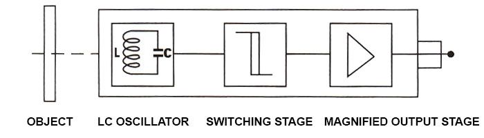
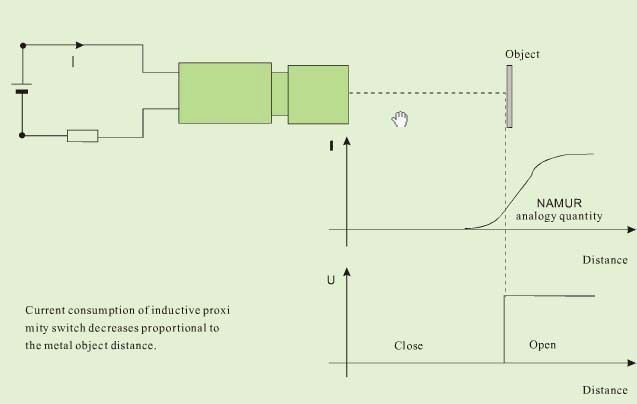
From object detection to the output signal
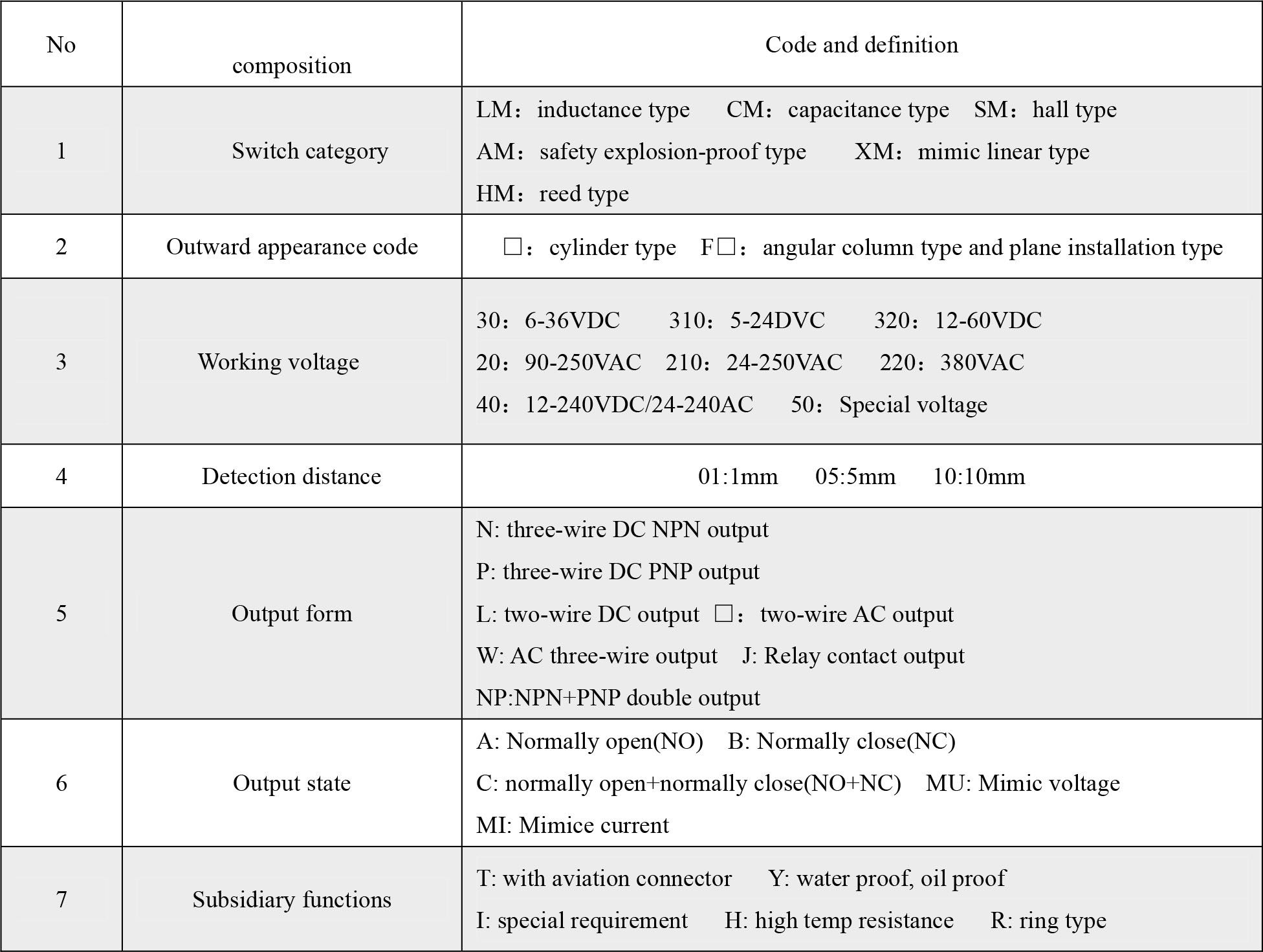
When a metal object approaches the detection zone, the sensor changes its output state. Catalogue descriptions list different housing sizes, supply ranges and output configurations, so the family name alone is not enough to determine how to connect the sensor.
Terms used in the documentation
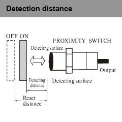
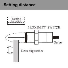
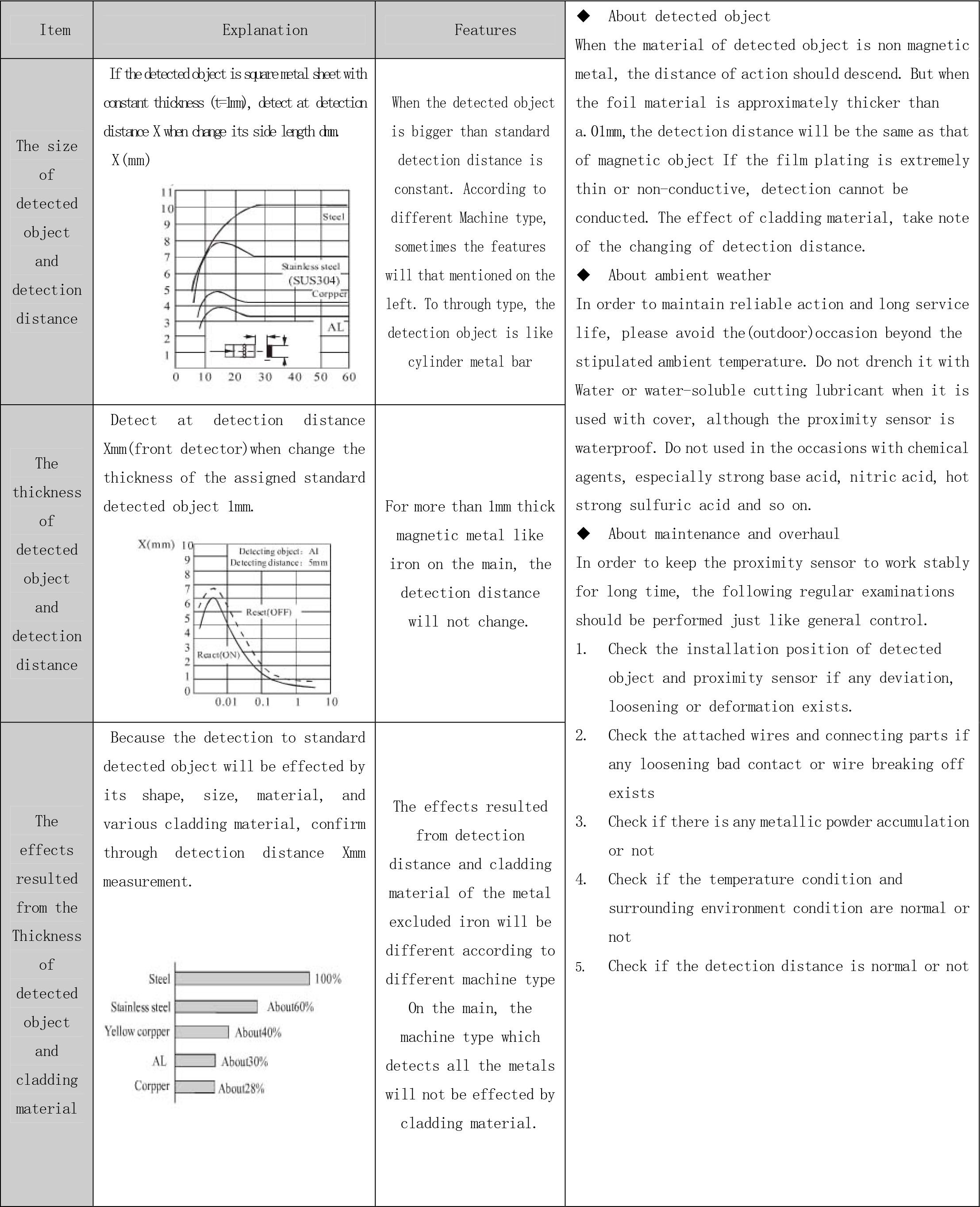
Sensing distance: the distance at which the sensor responds to a specified test object.
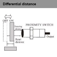
Hysteresis: the difference between the operating distance and the distance at which the previous state is restored.
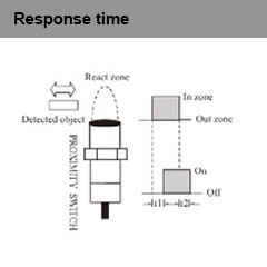
Response time: the time between a change in the object's position and a change in the output signal.
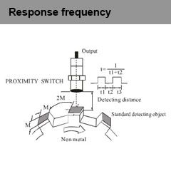
Switching frequency: the number of repeated detections, as specified by the measurement conditions in the documentation.
What should you compare before choosing?
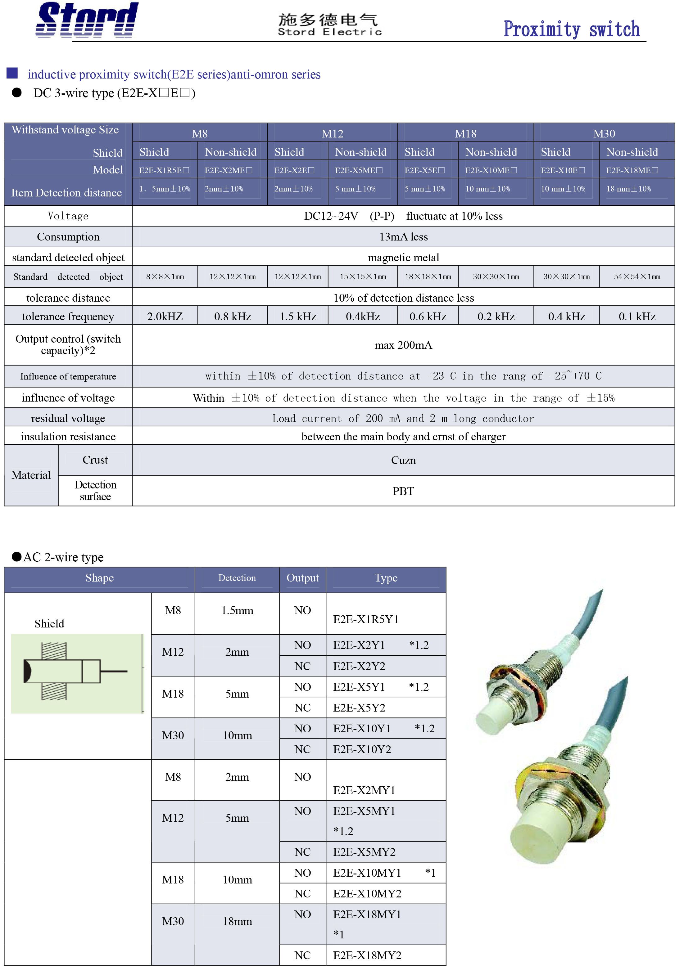
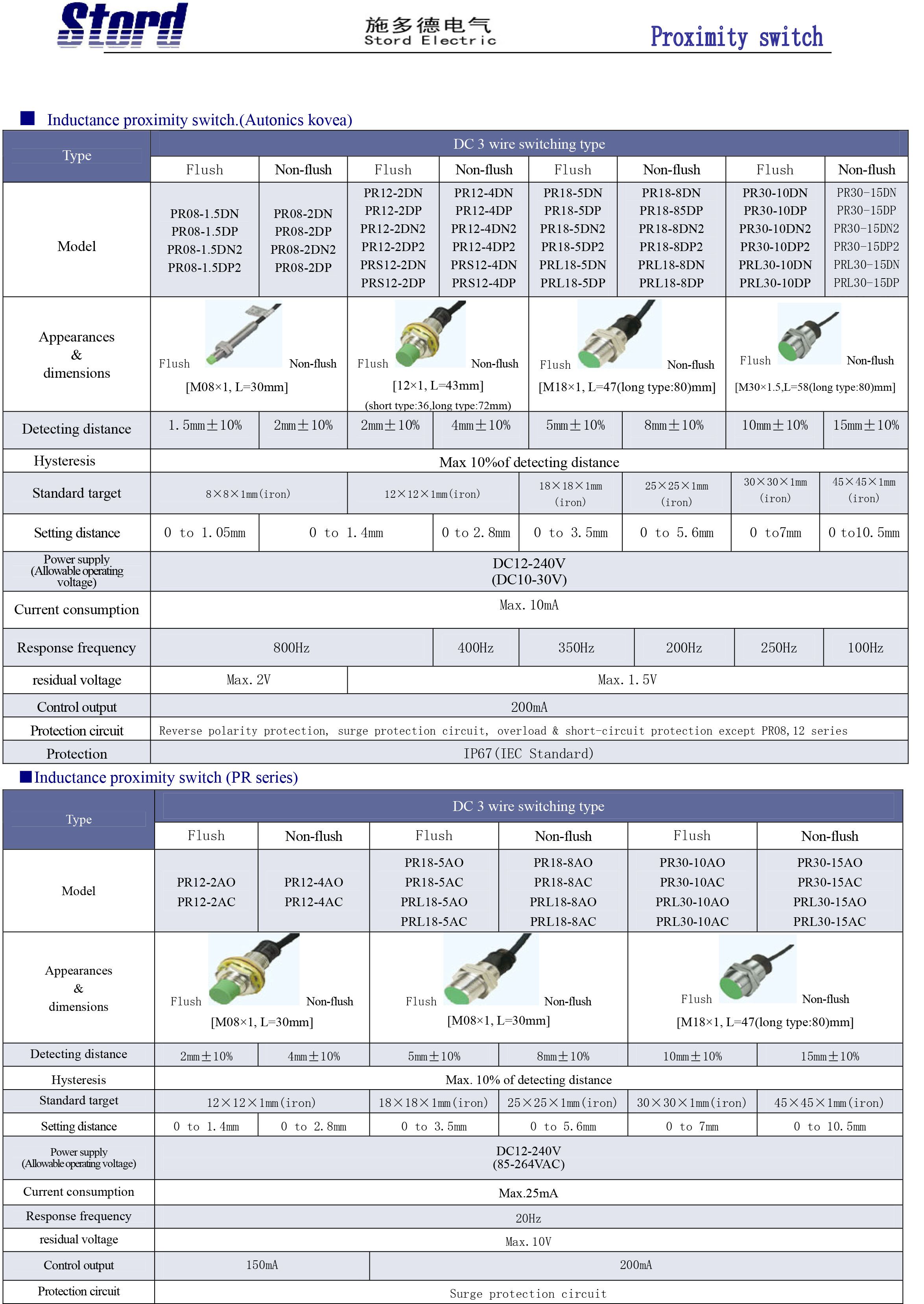
Selection involves the power supply, output type, dimensions, required distance and operating conditions. The stated characteristics must be checked for the specific model designation; do not assume that every model has all the features listed in the general catalogue.
Illustrations and catalogue data
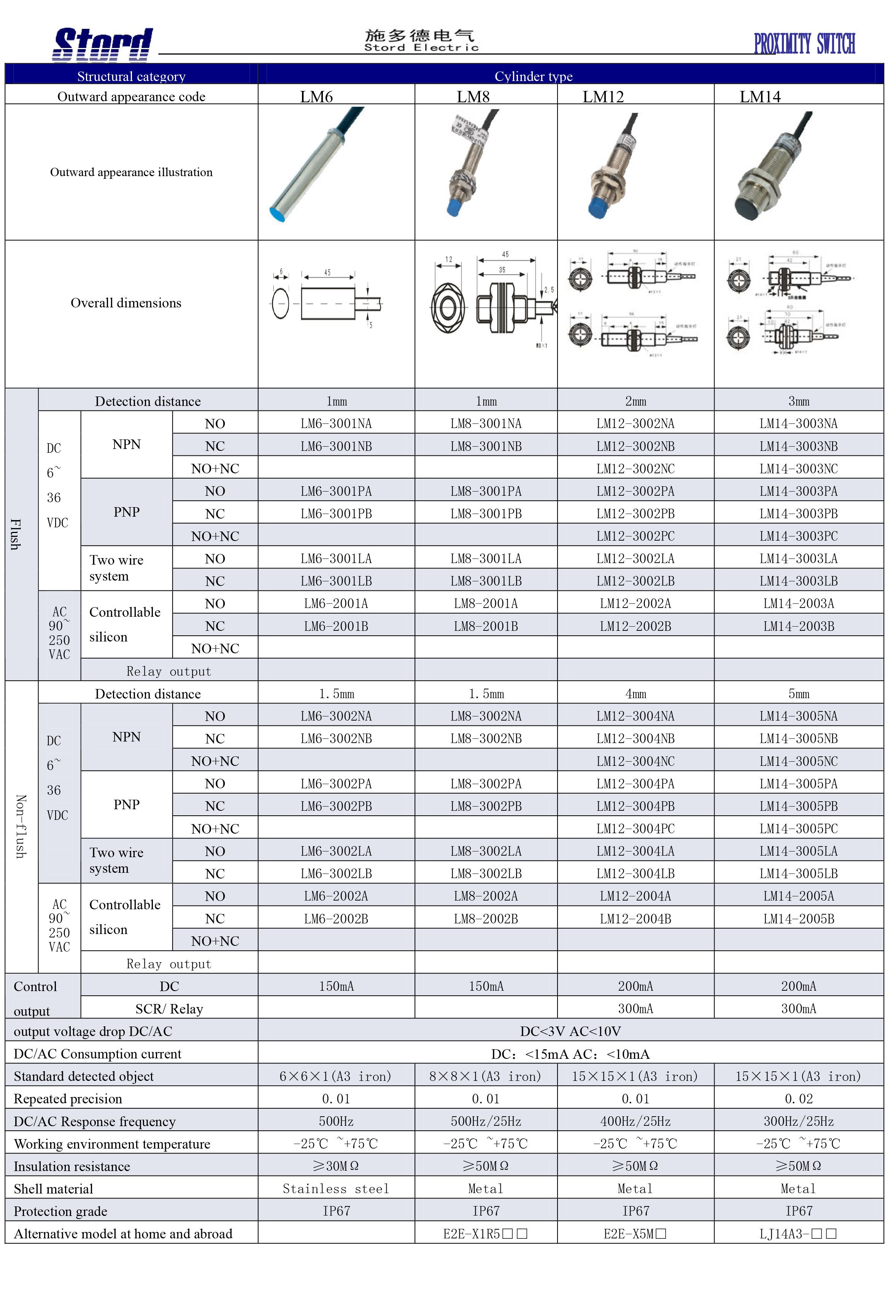
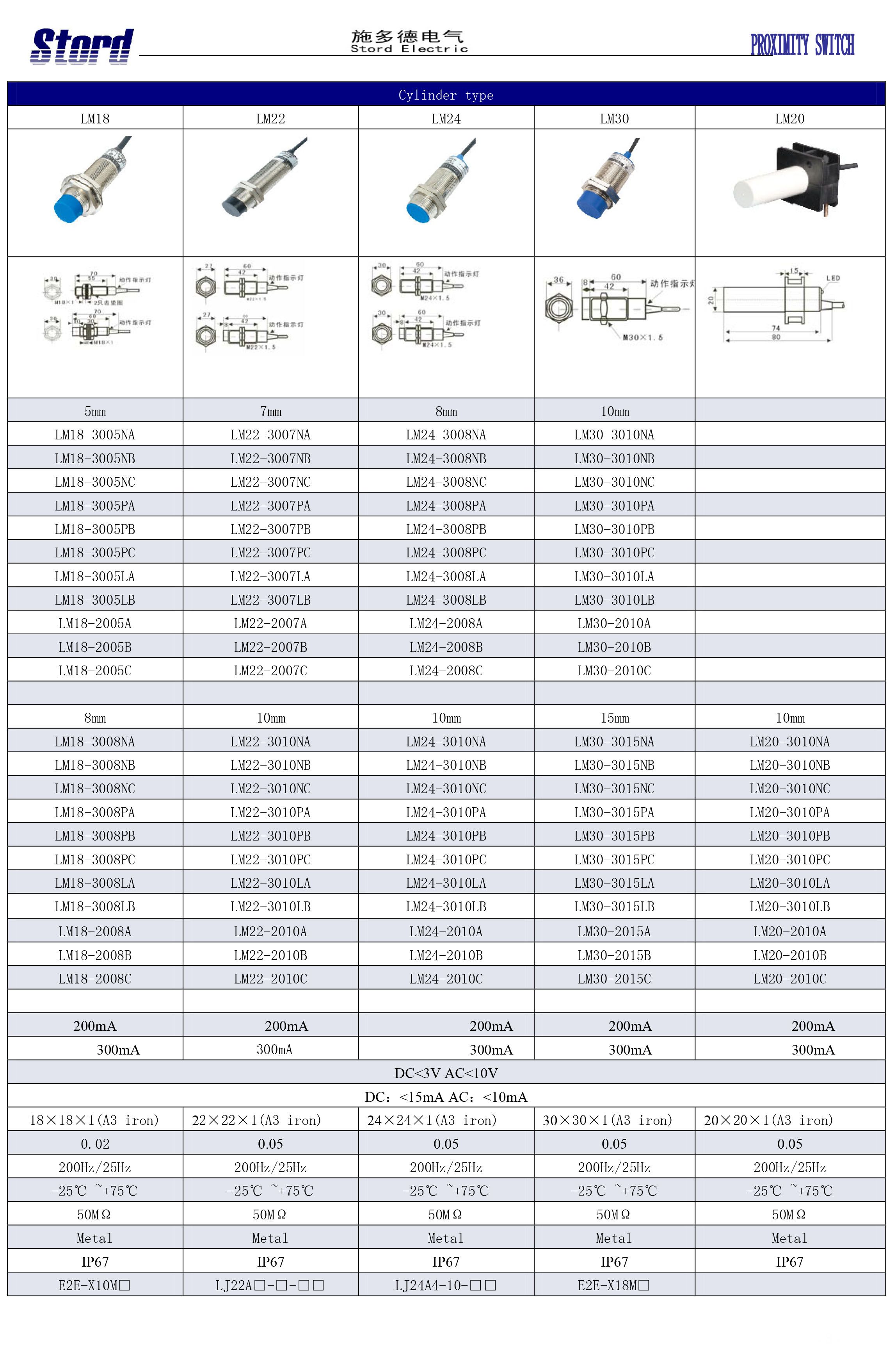
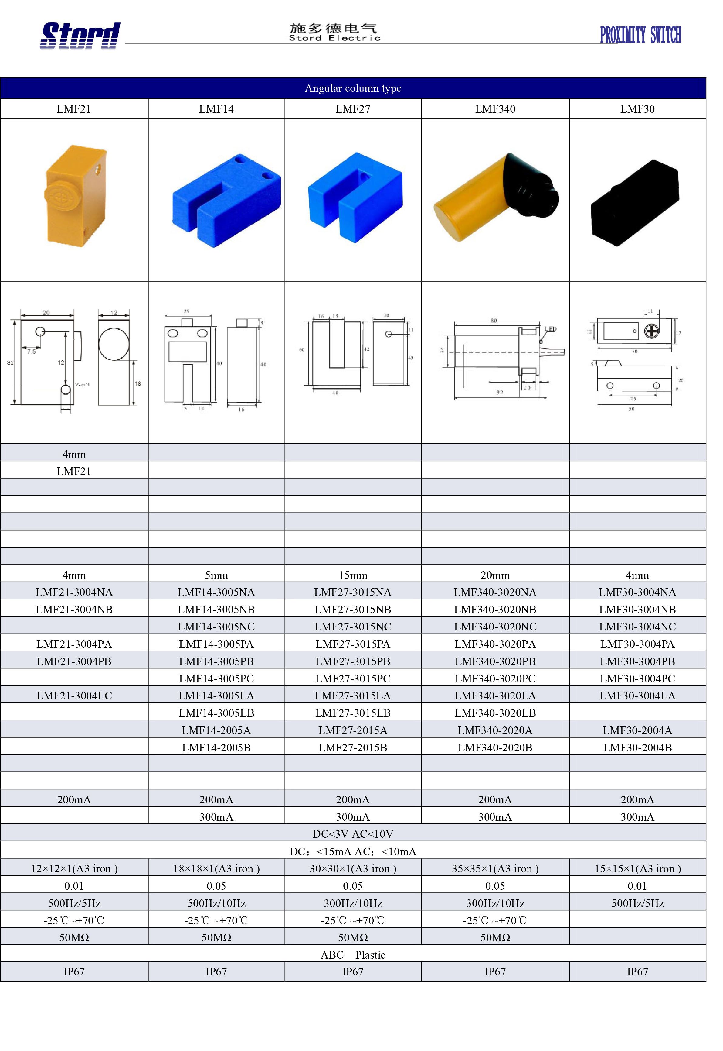
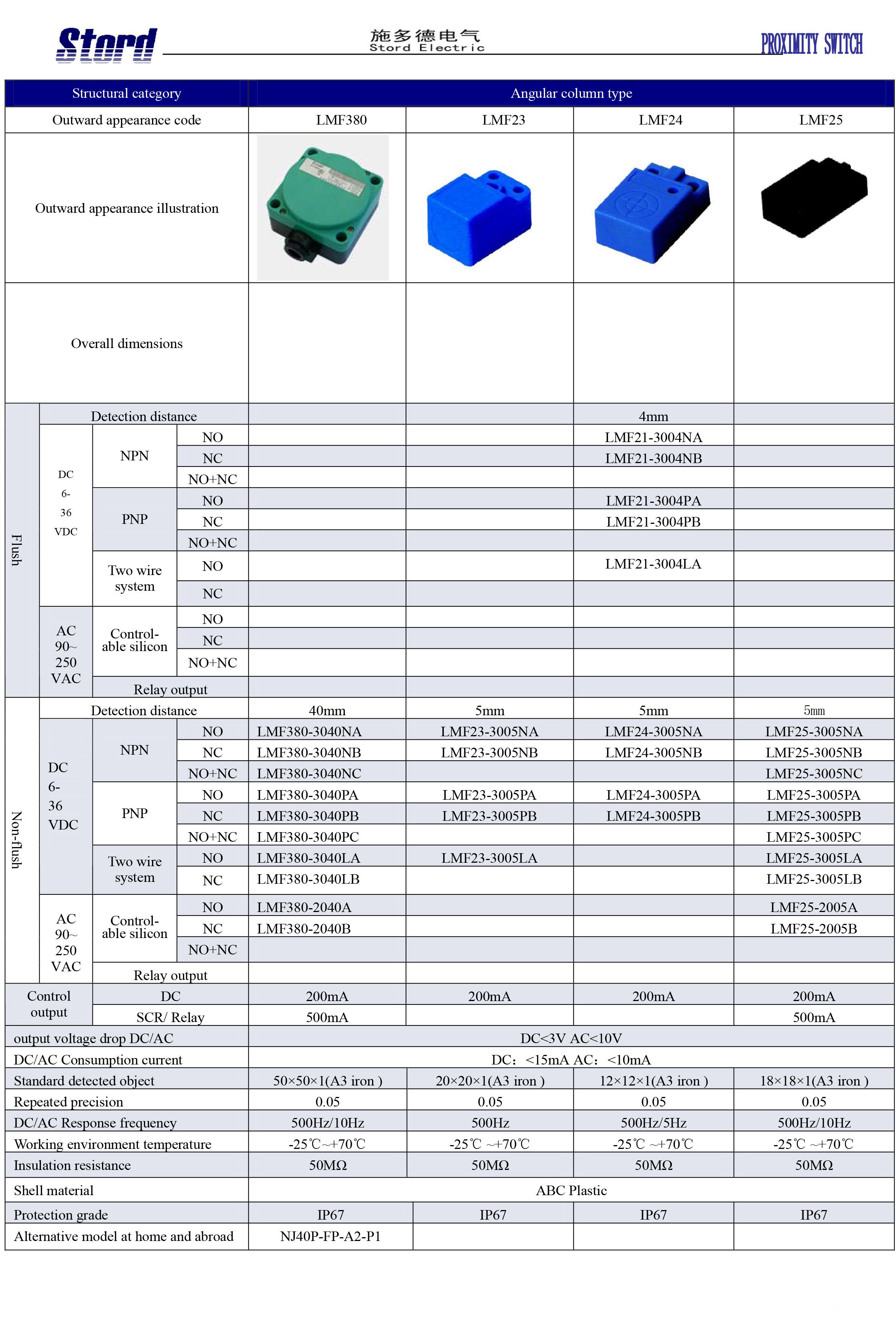
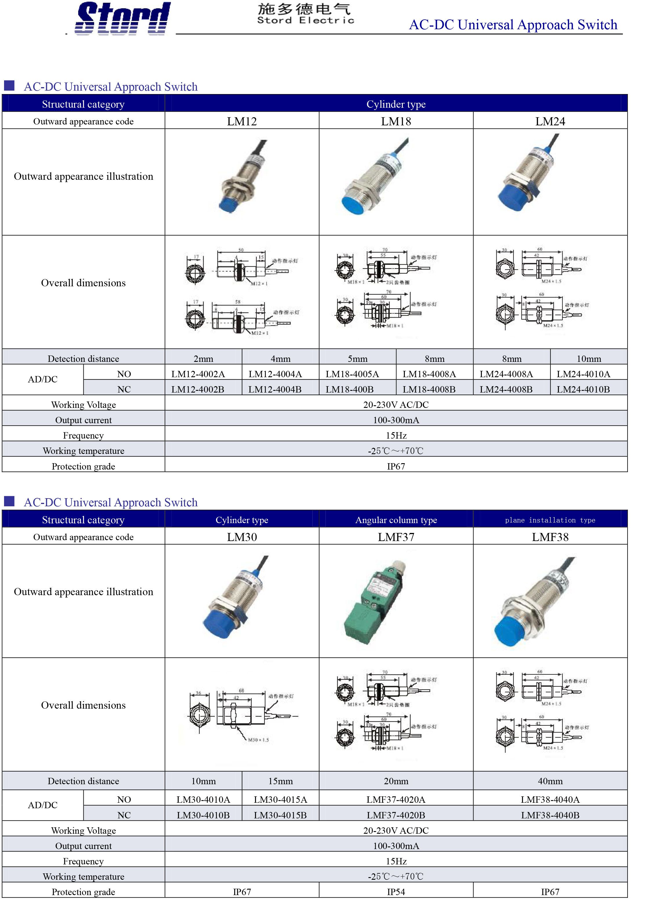
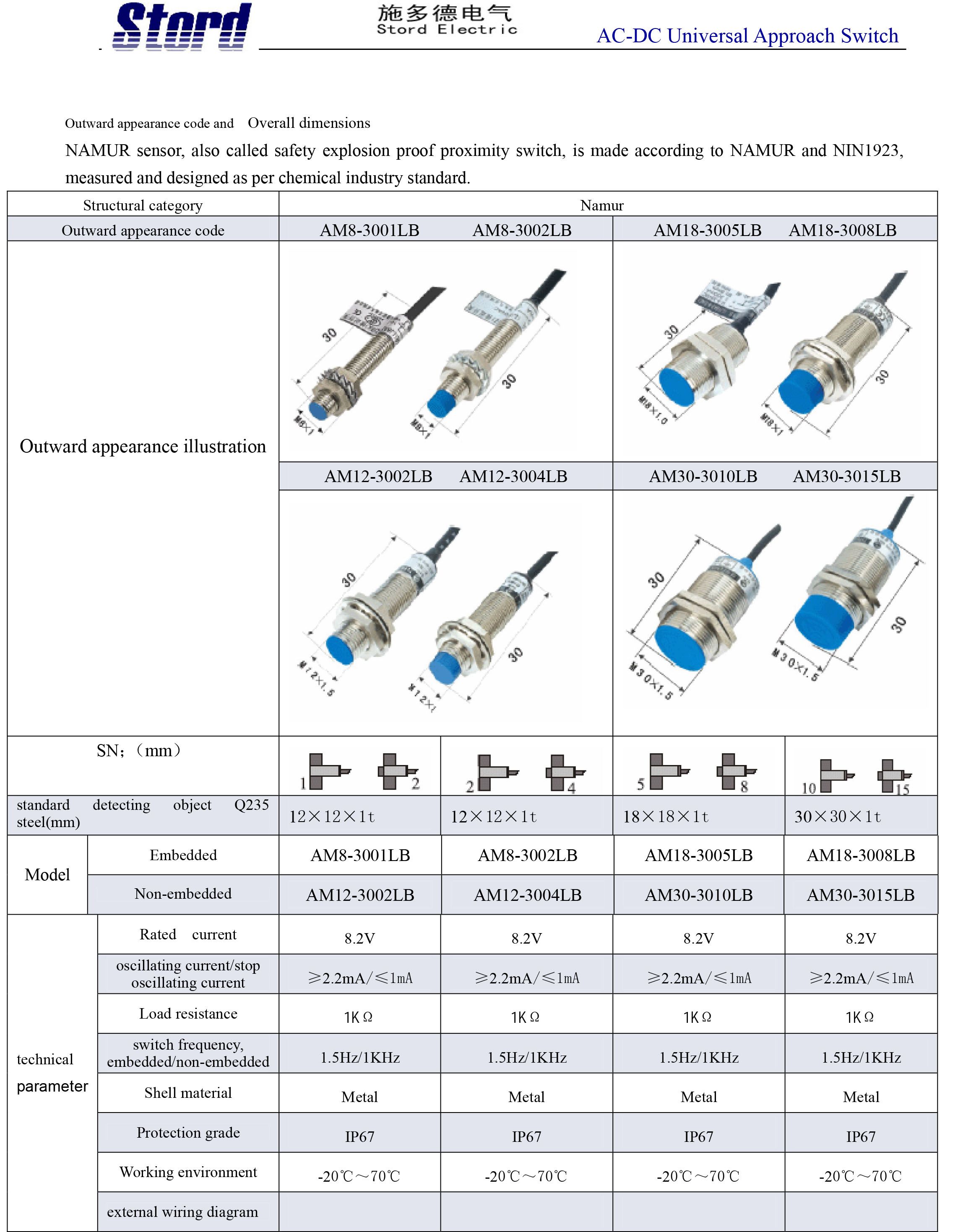
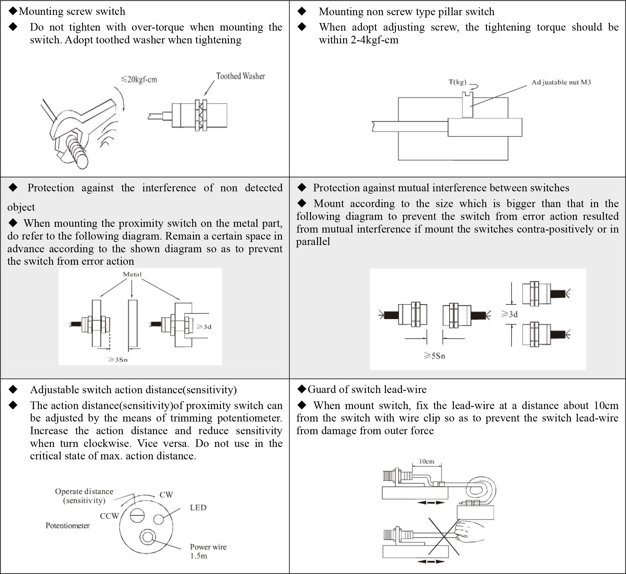
The compilations preserved below include, among others, the LM and LMF series and examples of AM models. These are original Stord source materials. Refer to the documentation for the selected model for the wiring diagram and installation instructions.
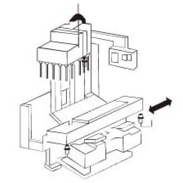
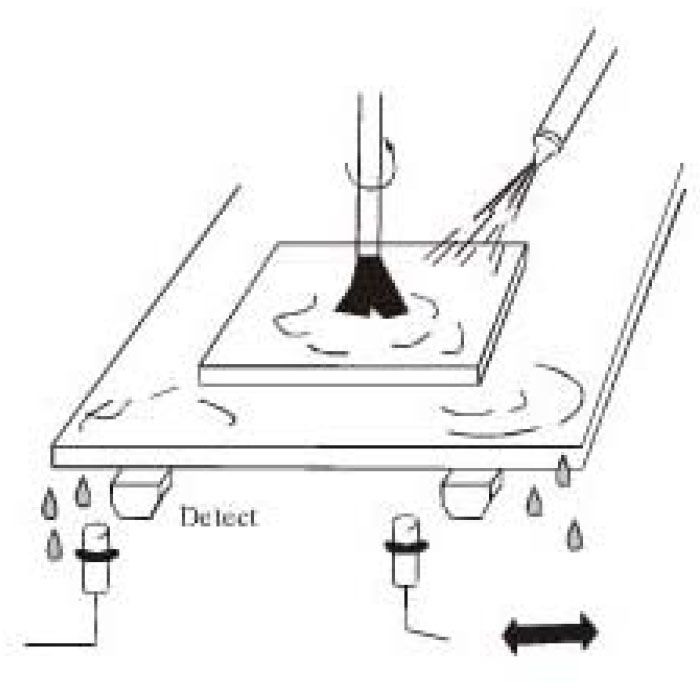
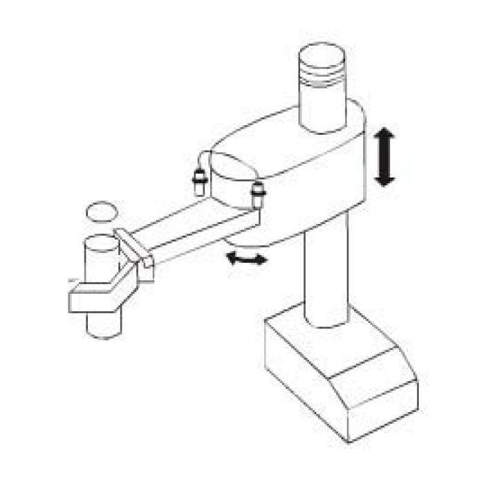
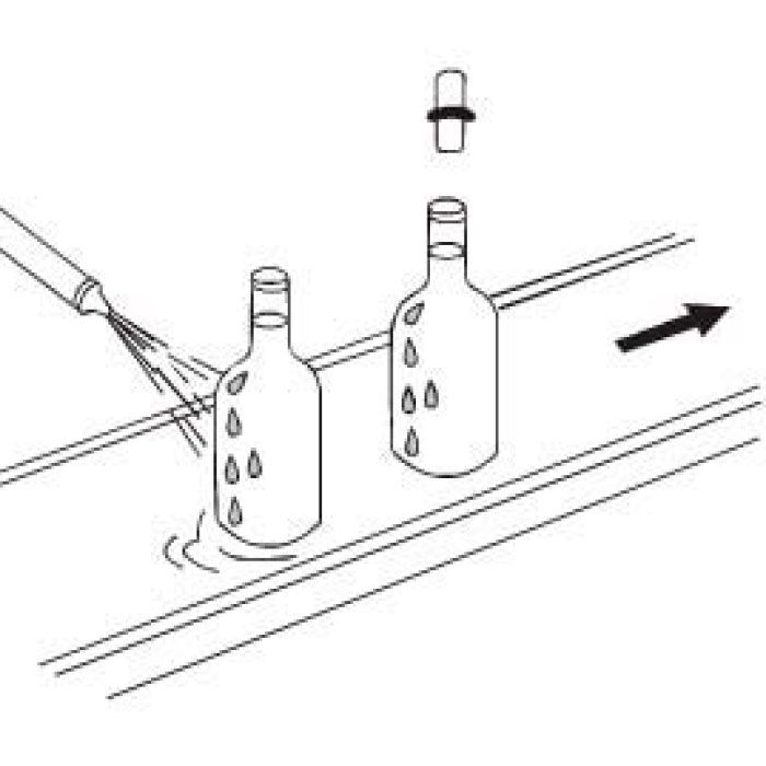
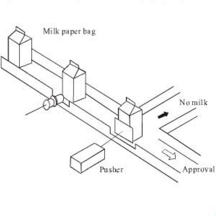
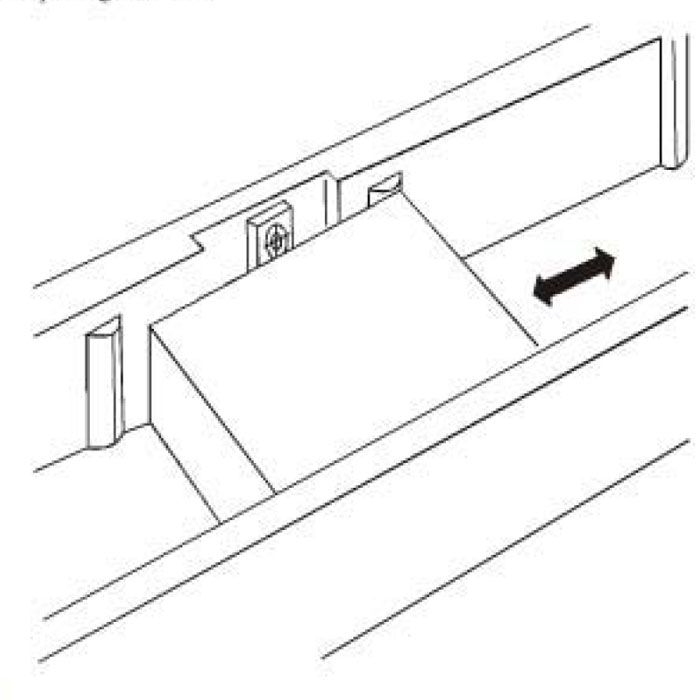
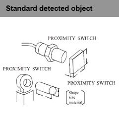
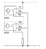
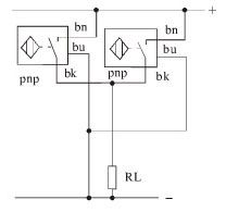
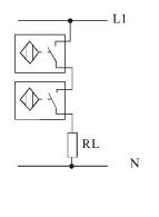
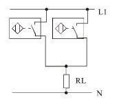
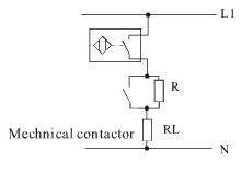
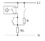
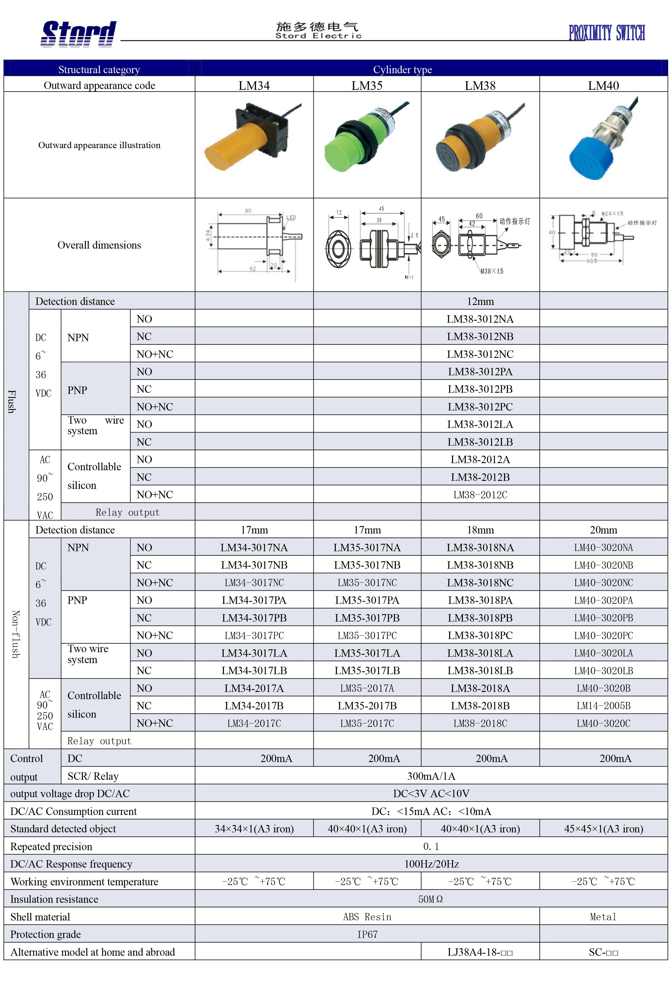
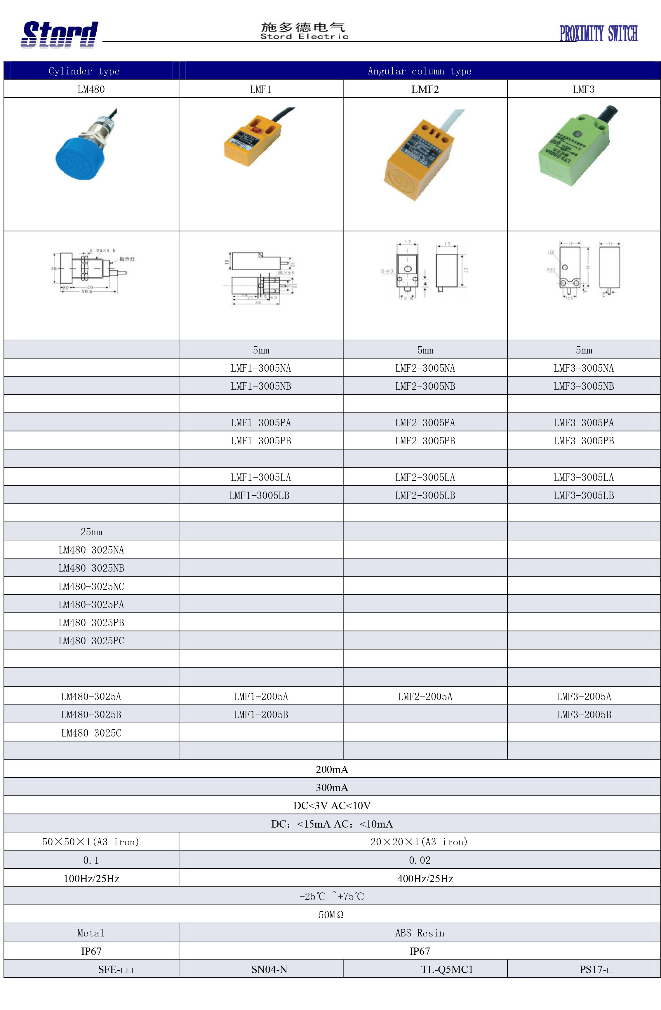
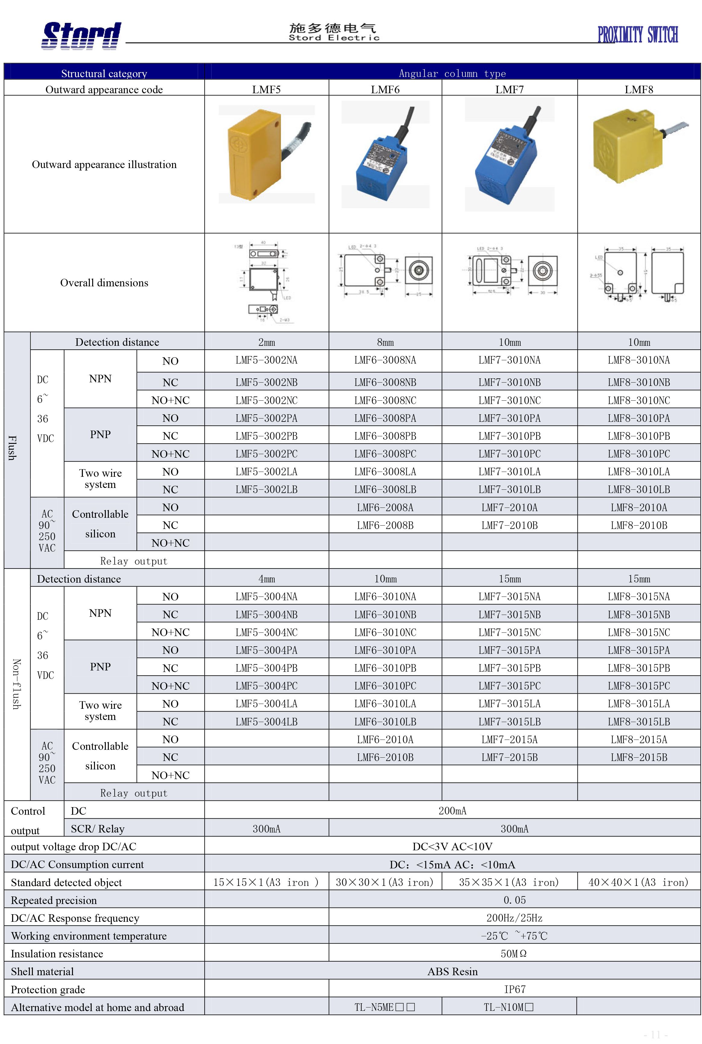
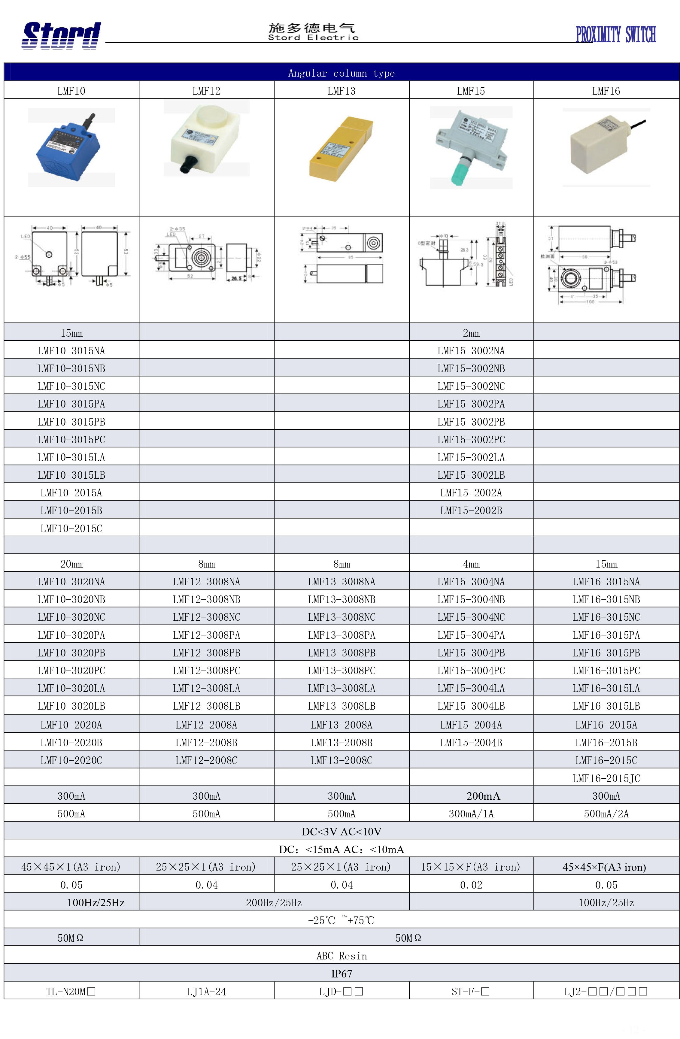
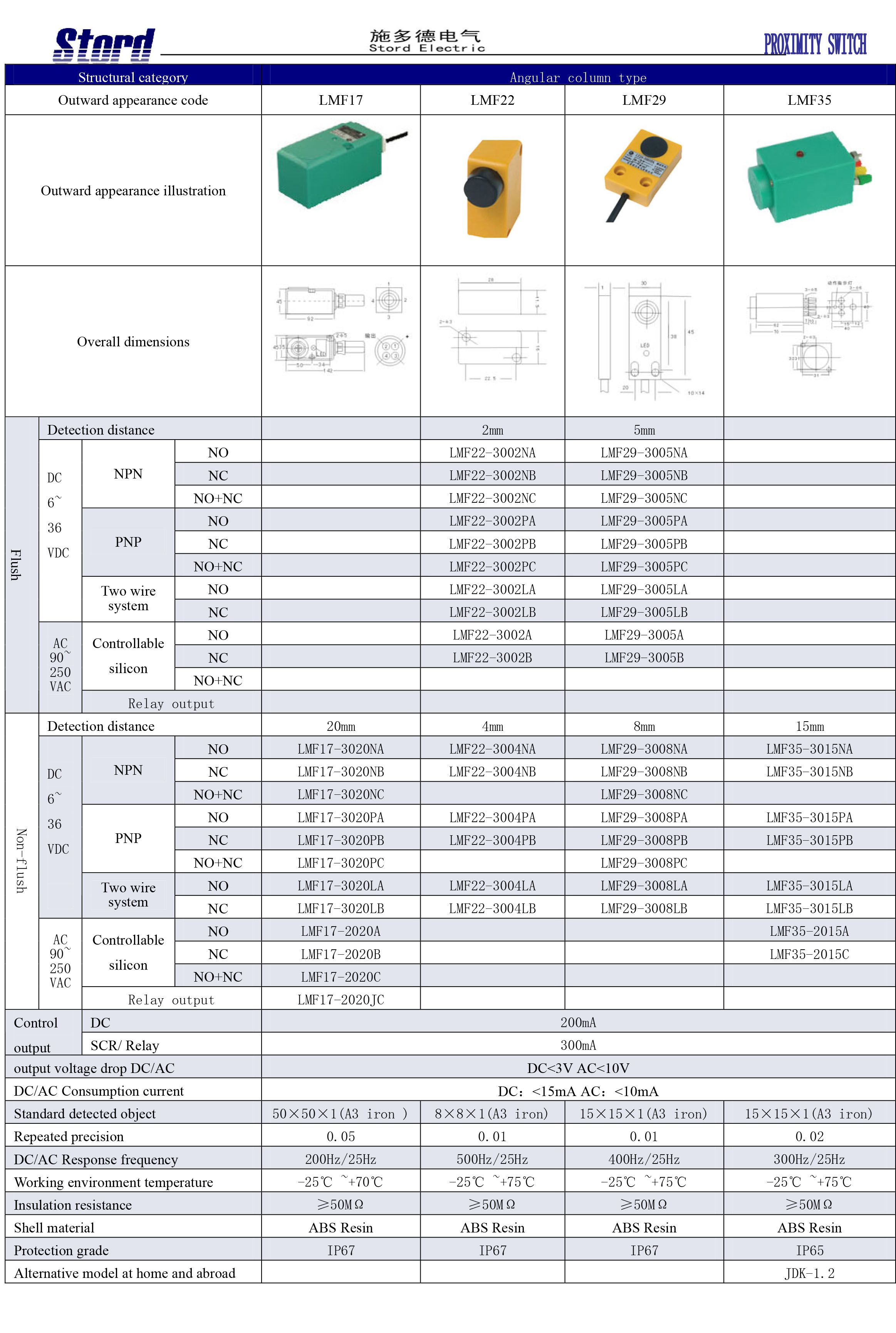
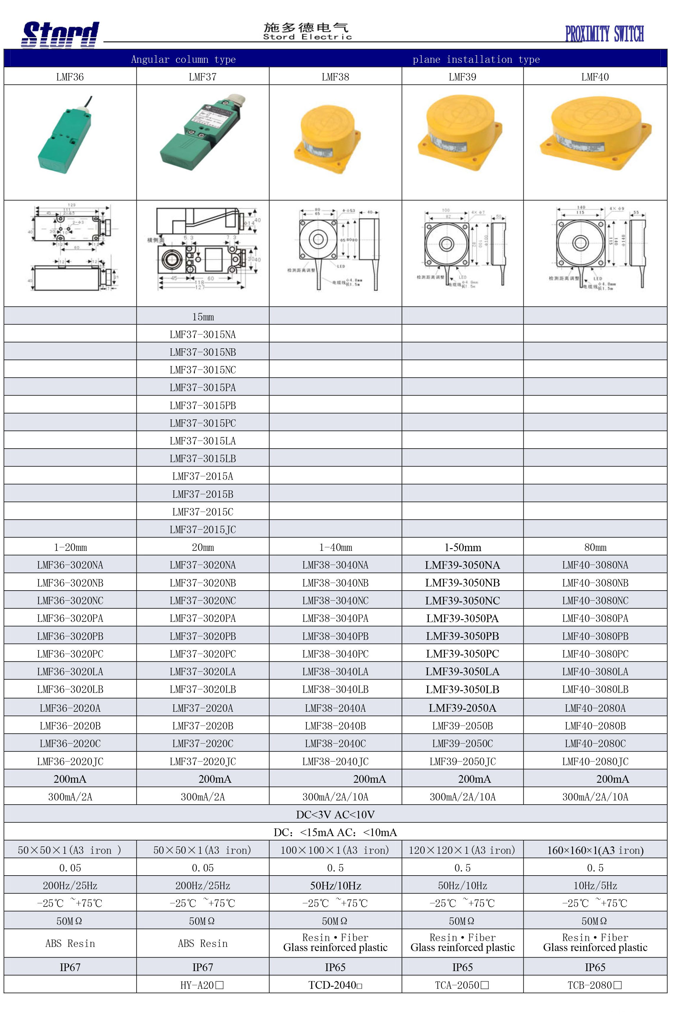
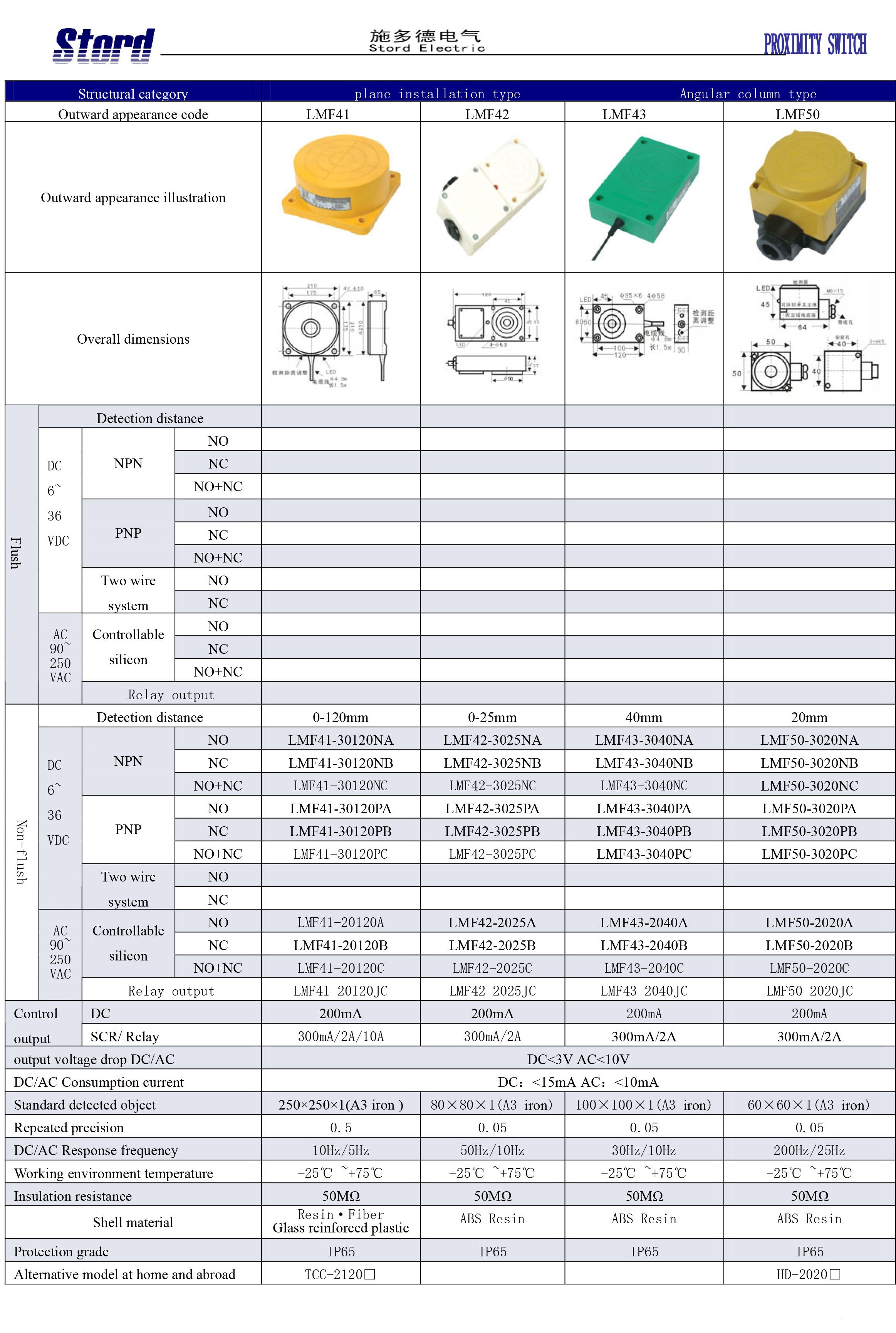
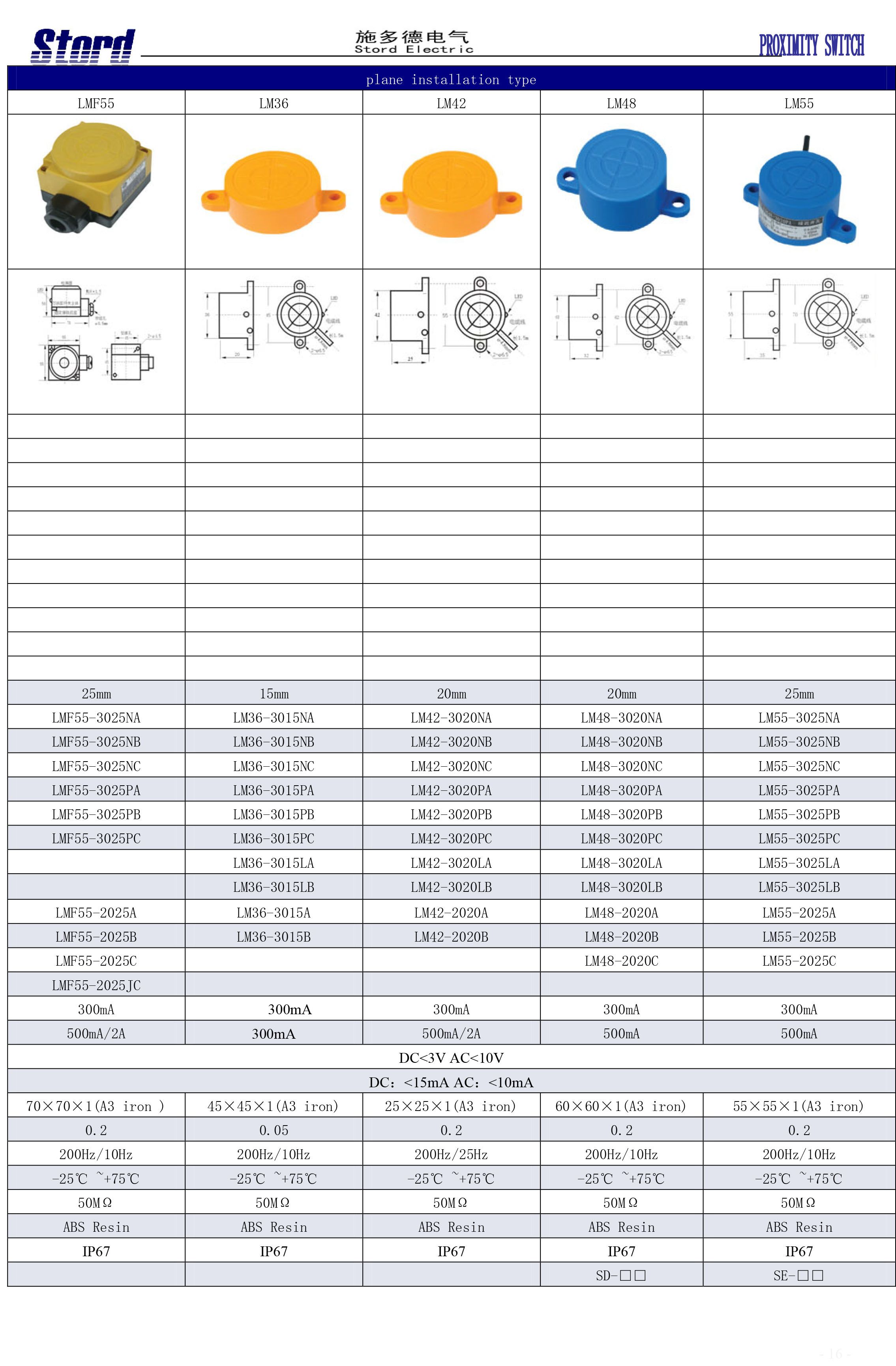
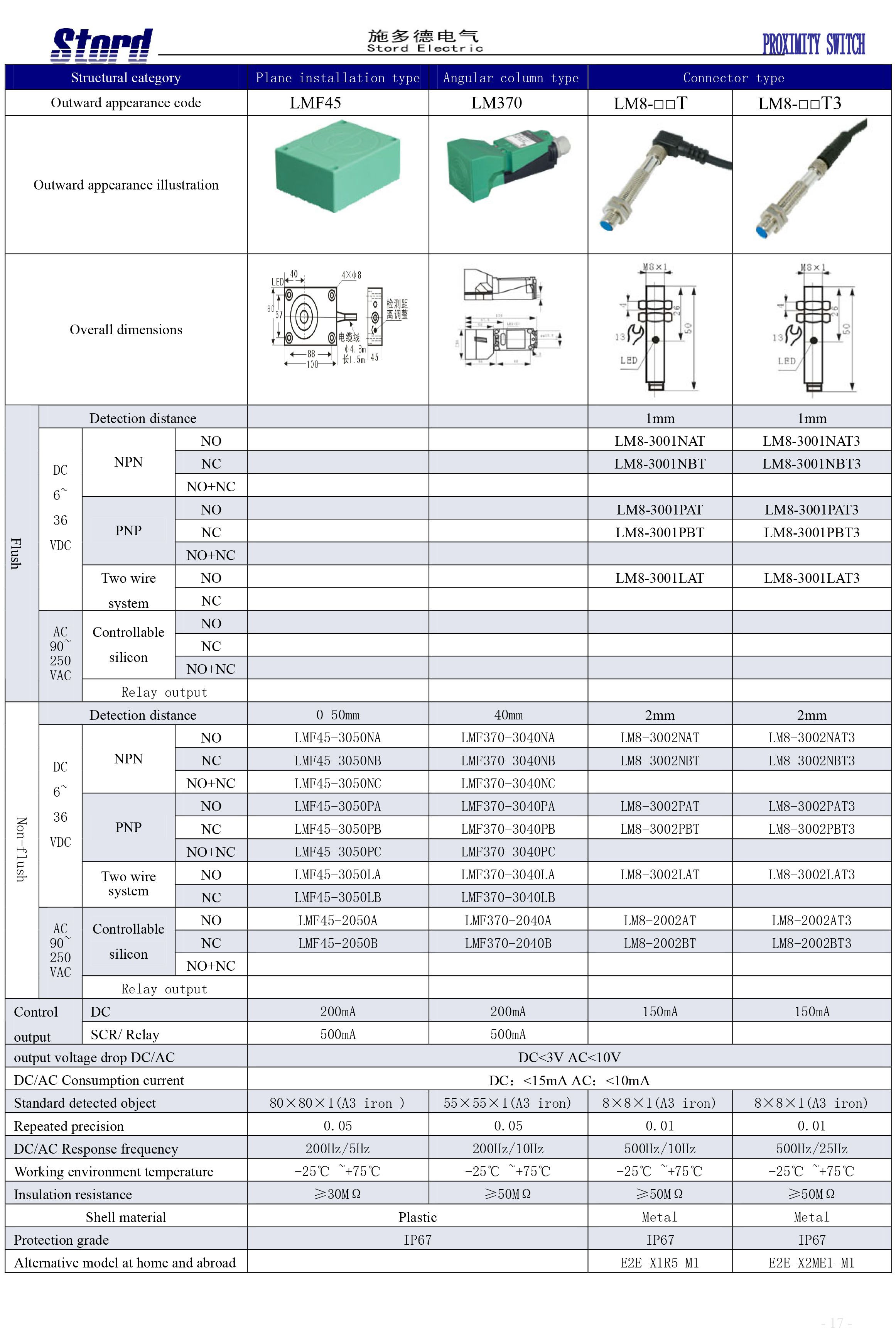
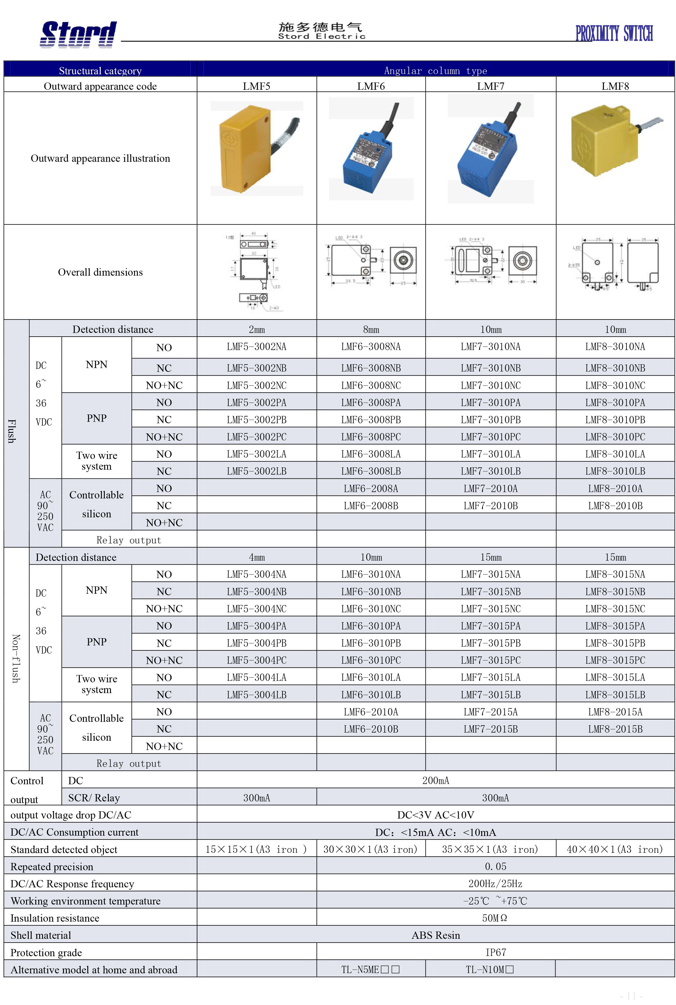
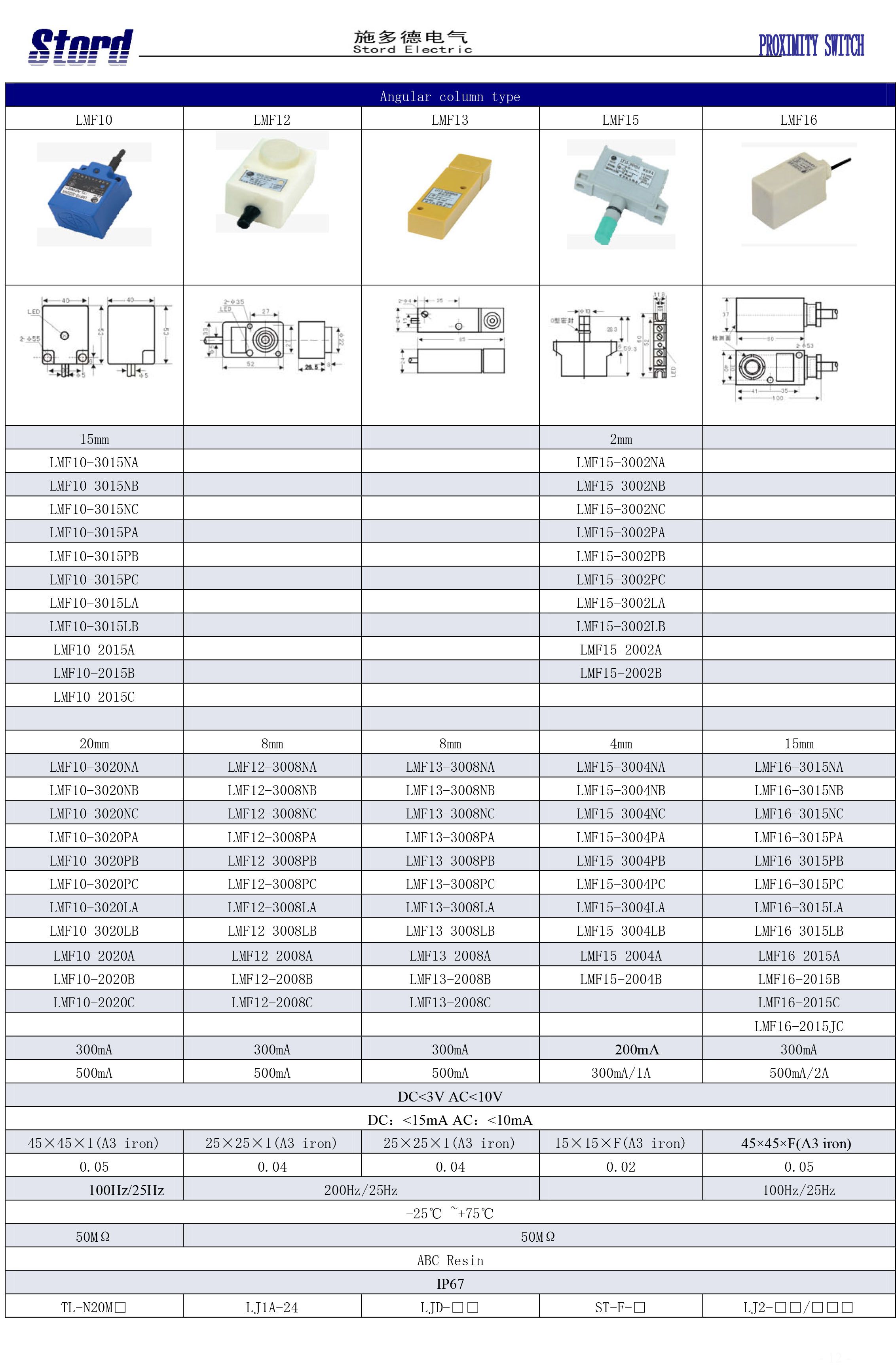
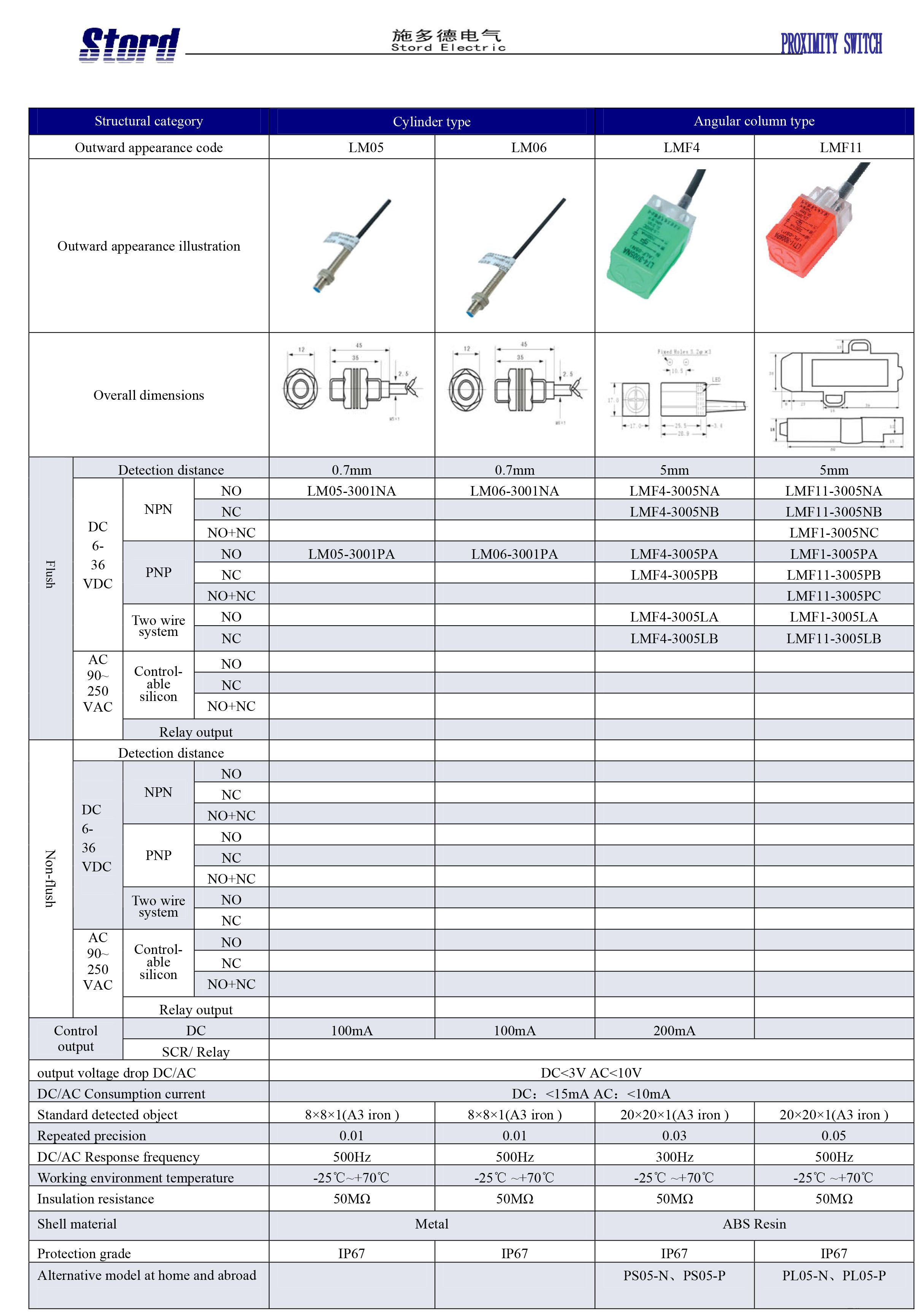
Various position detections in a machine process centreStopper detection on a grinding machineRobot arm position detectionBottle cap detectionChecking whether milk is present inside the cartonSpacing detectionMove the detected object according to the specified method; the distance from the reference position (reference plane) to the operating point (reset point).Taking account of effects such as temperature and voltage, this is the distance travelled from the practical sensing face to the target object without an error occurring.Use as a standard detected object to determine basic performance. Its shape, size and material are specified.The absolute value of the difference between the operating distance and the reset distance.T1: when the target object enters the operating zone, the time from the proximity sensor entering the operating state to the output appearing. T2: the time from leaving the operating zone to the output disappearing.Work out the number of output operations per second by repeatedly bringing the detected object closer. The diagram above shows the brief detection method.Series connection of a three-wire DC sensor and a three-wire DC sensorParallel connection of a three-wire DC sensor and a three-wire DC sensorSeries connection of a two-wire AC sensorParallel connection of a two-wire AC sensorSeries connection of a machinery switch and an AC sensorParallel connection of a machinery switch and an AC sensorSeries: LM6; LM8; LM12; LM14Series: LM18; LM22; LM24; M30; LM20Series: LM34; LM35; LM38; LM40Series: LM480; LMF1; LMF2; LMF3Series: LMF5; LMF6; LMF7; LMF8Series: LMF10; LMF12; LMF13; LMF15; LMF16Series: LMF17; LMF22; LMF29; LMF35Series: LMF36; LMF37; LMF38; LMF39; LMF40Series: LMF41; LMF42; LMF43; LMF50Series: LMF55; LM36; LM42; LM48; LM55Series: LMF45; LM370; LM8-□□T; LM8-□□T3Series: LM12-□T; LM12-□T3; LM18-□T; LM18-□T3; LM22-□TSeries: LM22-□T3; LM30-□T; LM30-□T3; LMF16-□TSeries: LM05; LM06; LMF4; LMF11Series: LMF21; LMF14; LMF27; LMF340; LMF30Series: LMF380; LMF23; LMF24; LMF25Series: LM12; LM18; LM24; LM30; LMF37; LMF38Series: AM8-3001LB; AM8-3002LB; AM18-3005LB; AM18-3008LB; AM12-3002LB; AM12-3004LB; AM30-3010LB; AM30-3015LB