Controller SC-S
A microprocessor-based climate controller belonging to the SPEED CONTROL family. A reliable controller, easy to install and operate, with software in Polish, English, Russian and German. The controller software allows intuitive setting of parameters: temperatures, intermittent ventilation, supplementary heating, min./max. ventilation levels and alarms.
Parameters and features:
- Group I ventilation:
- max. current of the continuously variable control output 6A,
- thermal protection of the system,
- ventilation soft start,
- minimum speed calibration
- Group II ventilation, isolated contact rated up to 3A (1 optional)
- Supplementary heating, isolated contact rated up to 3A (1 optional)
- Alarm outputs NO and NC:
- power failure indication,
- indication of temperature exceeding the min. or max. threshold
- 1 analog input for temperature measurement
- 2 outputs 0-10V
- Power consumption of the system < 3W
- Sealed enclosure IP56
- Supply voltage 230VAC 50Hz
Controller installation
The electrical power supply must be disconnected when installing the device, as the voltage present on some components poses a danger to life and health.
It is recommended that installation be entrusted to a qualified person.
Selecting the installation location
The installation location must be selected carefully, ensuring that the instrument is easily accessible to authorized persons, but inaccessible to animals and children. Climatic conditions must also be taken into account, i.e. the device should operate within a temperature range of -10°C to 40°C, in a location not exposed to direct sunlight. Air must be able to flow freely around the device. The device includes a temperature sensor. Several rules apply to temperature sensor installation:
- the sensor should not be installed in a location without air circulation or exposed to direct sunlight
- the sensor should not be installed on a load-bearing (external) wall of the building,
- avoid proximity to heat-emitting devices, such as heaters and lamps,
- the sensor must not be placed directly next to doors or ventilation openings,
- the sensor must not be placed in locations accessible to animals,
- it is recommended that the sensor connection cable be routed away from power cables.
Installation
The device can operate in harsh climatic conditions. When correctly installed, the controller and temperature sensor are resistant to environmental effects. During installation, attention must be paid to the following:
- check the cover gasket before fastening the cover,
- the cover must be secured with all screws,
- the cables used to connect the controller should be round,
- after connecting the cable, tighten the cable glands so that the cable is sealed and secured in place; the use of silicone is recommended,
- unused cable entries (glands) must be plugged,
- secure the controller (the lower part of the enclosure) to a flat wall using 4 wall plugs.
Electrical connection
Before connecting the system, make sure that the power supply is switched off!
Before connecting the controller, unscrew and remove the cover. Feed the cables through the rubber cable glands, then connect them. The controller terminals are shown in the figure below.
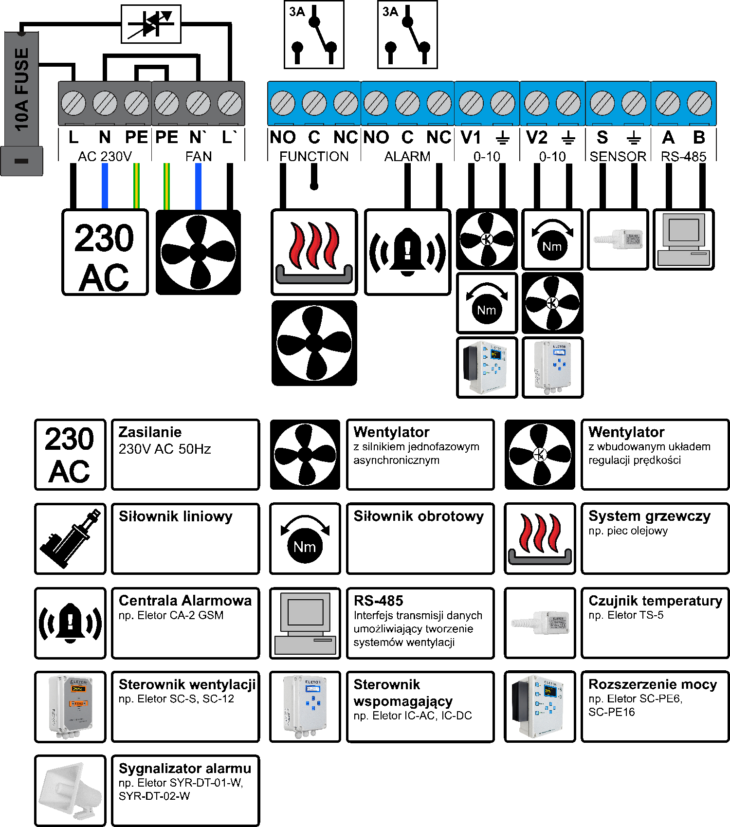
Connect the AC terminal 230V to the power supply (distribution board). An 1P-B6 overcurrent circuit breaker and type T1 T2 surge protection devices are required. When connecting several devices, it is good practice to group the controllers on different “phases” (L1, L2, L3) to distribute the load evenly across the supply line.
The FAN terminal must be connected directly to the fan; when controlling several fans, the total load must not exceed 6A, and each fan must be protected separately. Do not run PE and N from the power supply (distribution board); they must be connected to the controller terminals.
The FUNCTION terminal is an isolated relay output; the maximum contact current is 6A (an external 1P-B6 overcurrent circuit breaker is required when controlling a load directly),
and it can be used for:
- Supplementary heating – the contact closes when the measured temperature drops below the setpoint.
- Group 2 ventilation or sprinkler systems – the contact closes when the measured temperature is higher than the sum of the temperature setpoint and the ventilation band. the contact closes when the measured temperature is higher than the sum of the temperature setpoint and the ventilation band.
The figure below shows how to connect a group 2 fan or a heater.

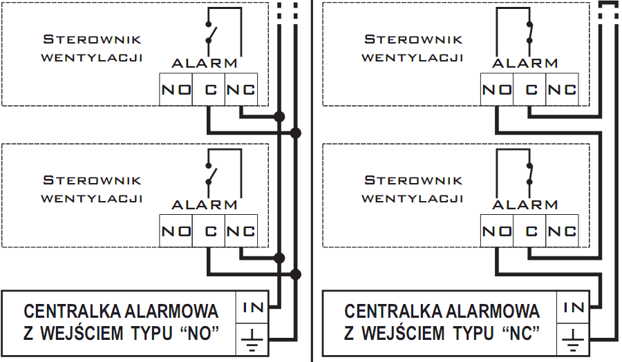
The ALARM terminal provides isolated NC, C and NO outputs for connection to an alarm control panel. The alarm is activated in the following cases:
- the temperature is too low or too high,
- the controller or temperature sensor is damaged,
- the controller supply voltage has failed;
- the controller has malfunctioned (e.g. controller overheating)
The V1 0-10V terminal is used to connect power expansion modules or fans with built-in speed control. The voltage at this terminal is proportional to the ventilation level.
The V2 0-10V terminal is used to connect an actuator that opens the air inlet flaps.
Connect the SENSOR terminal to an 1 temperature sensor TS3 or TS5; polarity does not matter. It is good practice to keep measurement cables away from power cables.
The RS-485 terminal can be used to build ventilation systems and communicate with a PC.
Operating principle
The controller's primary task is to maintain the temperature in the livestock room at the level set by the livestock farmer. It must be remembered that the controller is only a tool intended to help provide optimal climatic conditions in the livestock room. However, the livestock farmer plays the primary role in this process and should adjust the device settings to changing outdoor climatic conditions and, above all, to the requirements of the animals in the livestock building, and monitor the device's operating status using an alarm control panel.
Initial controller start-up
During initial controller start-up, the forbidden motor operating band must be set.
The controller works with fans based on single-phase asynchronous motors with a maximum total current consumption of 5A. After connecting the selected fans, the user must adapt them to operate with the controller. In other words, the minimum fan operating level (speed) must be set. This function is called “Forbidden Band” and is set once by the user under “Advanced Settings”. To perform this procedure correctly, assistance from a second person is recommended, so that one person can continuously observe the fan's behavior while the other sets the “Forbidden Band” value. Failure to set the forbidden band may lead to incorrect device operation. The “Forbidden Band” value can be considered correct when the pressure generated by the fan begins to lift the ventilation shaft flaps slightly. The “Forbidden Band” setting procedure must be repeated whenever the fan connected to the controller is changed.
Periodic intermittent ventilation
Intermittent ventilation is a function performed by the controller that is activated when the room temperature drops below the temperature setpoint. This function provides the animals with a periodic supply of fresh air. Intermittent ventilation is defined by 3 parameters:
- “Run Time” - specifies the number of seconds for which the fan is to be switched on,
- “Pause Time” - specifies the fan's idle time in seconds,
- “Intermittent Ventilation Level” - specifies the ventilation power during the “Run Time”.
An example setting of 60s/120s means that the fan is switched on for 60s with a pause of 120s between successive activations.
All the parameters listed above are set by the user. Several rules must be observed when setting intermittent ventilation parameters:
- intermittent ventilation is activated only when the temperature in the pig house drops below the temperature setpoint,
- the primary function of intermittent ventilation is to provide the animals with a periodic supply of fresh air, not to maintain the room temperature setpoint,
- it is recommended to ventilate rooms briefly but frequently,
- long intermittent ventilation periods should be avoided, as they may cause excessive temperature fluctuations,
- the parameters must be adjusted to the behavior of the animals and the conditions both inside and outside the room,
- the intermittent ventilation function can be disabled; in this case, in both percentage and time modes, zero values must be set in the field corresponding to the intermittent ventilation time value, e.g.: 0/120s
Continuously variable ventilation
The controller continuously adjusts ventilation from “Minimum Speed” to “Maximum Speed” within the range from the “Temperature Setpoint” to the sum of the “Temperature Setpoint” and the “Ventilation Band”. Above this range, ventilation group 2 is activated.
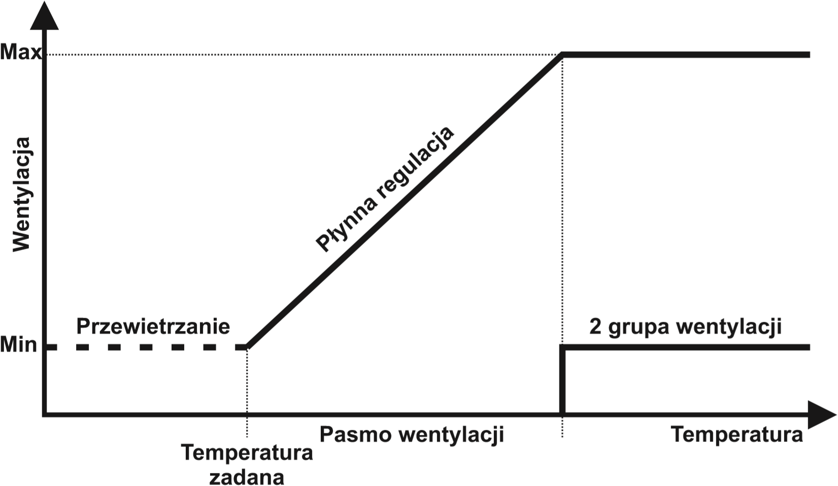
Above this range, ventilation group 2 is activated, If the room temperature drops below the “Temperature Setpoint”, the controller periodically ventilates the room; if the temperature drops further, supplementary heating is activated. Everything depends on the settings entered by the user. The controller software also supports operation with an alarm control panel, which can be activated when the temperature in the pig house deviates from the set parameters.
Controller programming
The controller has a set of default settings that are written to non-volatile memory in two cases:
- Initial device start-up,
- Data memory error.
In the event of a lack or loss of power, the controller retains the user settings previously entered and saved.
Using the menu
The controller is equipped with a range of functions that allow it to be adapted to a given application. These functions are grouped in a menu accessed by pressing one of the (“ Right Arrow”, “Left Arrow”) keys. Parameters are changed using the “+” and “-” keys; the edited parameter is automatically saved in non-volatile memory 30s after the last button press.
Basic menu functions
| MENU | Description |
|---|---|
| Temperature 20,8°C W16% A | “Information Mode” - normal operation. The display shows the current temperature and, when the fan is running, the ventilation level. Meaning of additional symbols: A-indicates an active alarm, D - indicates active heating, W - indicates additional ventilation |
| Temp. setpoint 20,0°C | “Temperature Setpoint” – the temperature value defining the start of the continuously variable ventilation process. |
| Intermittent ventilation 20s / 200s | “Intermittent Ventilation” – two time values are set: 1 “Run Time”, 2 “Pause Time” between successive periodic ventilation activations. |
| Intermittent vent. level 20% | “Intermittent Ventilation Level” - the ventilation level during intermittent ventilation operation |
| Minimum alarm 12,0°C | “Minimum Alarm” - specifies the absolute minimum temperature at which the alarm is activated. |
| Maximum alarm 28,0°C | "Maximum Alarm" - specifies the absolute maximum temperature at which the alarm is activated. |
| Supplementary heating 12,0°C | Depending on the configuration, the following functions are performed: “Supplementary Heating” - the contact closes if the temperature drops below the indicated value. |
| Stage 2 ventilation 25,0 | “Stage 2 Ventilation” - the contact closes when the measured temperature exceeds the sum of the temperature setpoint and the ventilation band. |
| Ventilation band 5,0°C | “Ventilation Band” - specifies the controller's response rate (changes in the ventilation level from minimum 1 to maximum 1) to rising temperature. |
| Minimum speed 1% | “Minimum Speed” – a state in which the device remains indefinitely, supplying a voltage of the set value to the output. Used to calibrate the device with the motor and flap mechanism. |
| Maximum speed 100% | “Maximum Speed” – a state in which the device remains indefinitely, supplying a voltage of the set value to the output. Used to limit the power allocated to ventilation |
Advanced menu
The advanced menu is intended primarily for installers and allows the controller to be adapted to the installation and fan. Advanced settings are accessed by pressing and holding the two menu keys for approximately 10s.
| MENU | Description |
|---|---|
| No advanced settings | This message indicates that the controller has not been calibrated with the ventilation system and may operate incorrectly. It is necessary to enter the advanced menu and configure the “Forbidden Band” settings. |
| Advanced Settings | Indication of entry into advanced settings. |
| Software Ver: 1907 | Software version information. |
| Forbidden band 1000 us | Calibration of the minimum speed of fans connected directly to the controller; this parameter corresponds to ventilation level “1%” |
| Contact function Supplementary heating | Selection of contact function: • Supplementary heating (default) • Group 2 ventilation |
| Intermittent ventilation Time-based | Selection of intermittent ventilation type: • Time-based (default) • Percentage-based |
| Range V1 from 2,0 to 10,0 | Adjustment of the voltage variation range at output V1 0÷10V. The settings apply to the minimum and maximum voltage values. The adjustment is used to adapt the controller to a power expansion module or frequency inverter. |
| Inversion V1 No | Activation reverses the characteristic of output V1. The voltage decreases as the ventilation level increases within the range defined by min.-max. The signal at output V1 will be of type 10-0V. |
| Cutoff V1 No | Activation causes output V1 0-10V to provide level 0V instead of the set minimum value when the ventilation level is 0%. |
| Range V2 from 2,0 to 10,0 | Adjustment of the voltage variation range at output V2 0÷10V. The settings apply to the minimum and maximum voltage values. The adjustment is used to calibrate the flap system. |
| Inversion V2 No | Activation reverses the characteristic of output V2. The voltage decreases as the ventilation level increases within the range defined by min.-max. The signal at output V2 will be of type 10-0V. |
| Temp. calibration 21,0°C -> 22,0°C | Temperature sensor calibration allows the measured value to be rescaled. |
| Soft start 50% | Specifies the ventilation level at each fan start; the fan accelerates to the indicated value, then transitions to the set level. |
| Language Polish | Menu language selection: Polish, English, German, Russian |
| Exit | Exit the advanced menu using the “+” key; the changes made will be saved in non-volatile memory. |
Error and warning messages
Error messages inform the user of irregularities in controller operation. Possible error messages are listed below.
| ERROR | DESCRIPTION |
|---|---|
| Overload Alarm | Overload alarm, activated at 75°C. The device suspends operation until it cools down. |
| SENSOR OPEN CIRCUIT! Check sensor | Open-circuit sensor; indicates damage to the sensor or connection cable. |
| SENSOR SHORT CIRCUIT! Check sensor | Short-circuit sensor; indicates damage to the sensor or connection cable. |
| Power Failure | Power failure, supply voltage too low, incorrect frequency or severely distorted supply voltage. |
Notes and warnings
The electrical power supply must be disconnected when installing the device, as the voltage present on some components poses a danger to life and health. It is recommended that installation be entrusted to a qualified person.
- To avoid problems with device operation, the manual must be read before installation and use.
- The construction must not be modified, nor may repairs be performed independently. This applies in particular to modifications of parts and components.
- Maintenance or servicing must be performed by authorized personnel (an installer or the manufacturer's service department). An alarm system is required in livestock buildings with forced ventilation. The device manufacturer is not liable for damage caused by incorrect installation, incorrect programming of functions, the consequences of unforeseen events or external factors.
- The ventilation controller requires its parameters to be set in accordance with the conditions in the livestock room. These settings are individual and depend on the livestock farmer's decisions. The device manufacturer reserves the right to make changes to the device construction and software.
 At the end of the product's service life, do not dispose of it with unsorted municipal waste; instead, dispose of it in accordance with applicable regulations (European Union WEEE Directive 2012/19/EU).
The product has been manufactured in accordance with RoHS requirements (European Union Directive 2011/65/EU).
Controller technical specifications
| Parameter | DESCRIPTION |
|---|---|
| Supply voltage | 230VAC 50Hz |
| Maximum current of the FAN continuously variable control output | 6A |
| Output voltage control range | 70V ÷ (Uz-5)V |
| Maximum ALARM output (contact) current | 3A |
| Maximum FUNCTION output (contact) current | 3A |
| Operating temperature range | -20 +40oC |
| Temperature measurement range | 0 +50°C |
| Temperature measurement resolution | 0,1°C |
| Temperature sensor fault detection | YES |
| Maximum number of analog sensors | 1 |
| Temperature measurement accuracy – analog input | 1°C |
| Measurement dependence on cable resistance – analog input | 15,8Ω/°C |
| Surge withstand capability (max E) | 210J |
| Overload protection | 75°C |
| Device dimensions | 20x15x8 [cm] |
| Enclosure ingress protection rating | IP56 |
The SPEED CONTROL SERVOMOTOR controller package includes:
- 1 temperature sensor + accessories,
- 4 wall plugs,
- 1 fuse 10A.