Power supply DC50W24VB
Backup power supply with automatic and manual opening of air inlets and outlets. Used to ensure the safety of livestock in the event of a power failure or controller malfunction. Upon detecting an abnormal condition, the device will signal an alarm and open the winches to the preset level.
Parameters and features:
- Operating mode selector switch:
- MANUAL
- AUTO.
- Air inlet opening adjustment knob.
- Supported standards:
- 0-10, 2-10, 10-0, 10-2.
- Control signal inversion capability.
- Alarm outputs NO and NC.
- Power failure indication.
- Control voltage monitoring 2-10V.
- Short-circuit monitoring of 24VDC outputs.
- Short-circuit monitoring of 0-10V outputs.
- 2 input 0-10V.
- 2 outputs 0-10V.
- Electronic protection of inputs, outputs and the 24V line.
- Battery bank 24V 4.0 Ah.
- Sealed enclosure IP65.
- Supply voltage 85
264VAC 4763Hz.
Controller installation
The electrical power supply must be disconnected during installation of the device, as the voltage on some components poses a danger to life and health. It is recommended that installation be entrusted to a qualified person.
Selecting the installation location
The installation location must be selected carefully, ensuring easy access to the device for authorized persons while keeping it inaccessible to animals and children. Climatic conditions must also be taken into account, i.e. the device should operate within the temperature range of -10°C to 40 °C, in a location not exposed to sunlight. Air must be able to flow freely around the device.
Installation
The device can operate under harsh climatic conditions. When correctly installed, the device is resistant to harmful environmental effects.
During installation, attention must be paid to the following:
- the cover must be secured with all screws tightened,
- cables used to connect the device should have a circular cross-section,
- after connecting a cable, tighten the cable glands so that the cable is sealed and secured in place; the use of silicone is recommended,
- unused cable entries (cable glands) must be plugged,
- secure the lower part of the enclosure to a flat wall using 4 wall plugs.
Electrical connection
Before connecting the system, make sure that the power supply is switched off!
After unscrewing the device, remove the front panel. To do this, pull the ribbon cable out of the connector marked P1. Route the cables through the rubber cable glands and proceed with connecting them. The connections must be made as described.
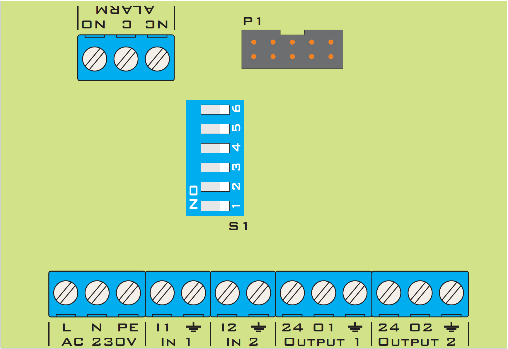
Power supply 230V AC: connect to the power supply (distribution board). An overcurrent circuit breaker (type “S” B6) and class “C” surge protective devices must be used. The device can be powered over a wide voltage range from 85V to 264V and a frequency range from 47 to 63Hz, without affecting device operation.
In1 and In2 connector must be connected to the controller to supply a control signal to the winch systems. The device can support two controllers or a single controller with separate inlet and outlet sections (terminals I1 and I2 must be bridged).
ALARM connector connect to the alarm control panel, depending on the system – closed (NO and C), open (NC and C). The alarm is activated in the following cases: •the device supply voltage has been lost, •the 2-10V control signal has been lost on at least one input, •the output signal has been short-circuited or its value differs from the measured value, •a short circuit has occurred on the +24V bus supplying the winches.
Ouput 1 and Ouput 2 connectors connect to the actuator (winch) as required for the device in use; the connection description should be provided in the manual for the respective actuator (winch).
Operating mode switch S1 select the appropriate operating mode depending on the actuator (winch) in use. By default, the 1,2,3,4,5,6 switches are in the off position – 2-10V operation.
| Channel 1 | Channel 2 | Function |
|---|---|---|
| 1 – off | 4 – off | Operating mode within the 2-10V signal range; a control voltage below 1,5V generates an alarm. |
| 1 – on | 4 – on | Operating mode within the 0-10V signal range; no alarm response to a signal below 1,5V. |
| 2 – off | 5 – off | Proportional operating mode, output signals within the 0-10V or 2-10V range. |
| 2 – on | 5 – on | Reversed operating mode, output signals within the 10-0V or 10-2V range. |
| 3 – off | 6 – off | Input inversion disabled. |
| 3 – on | 6 – on | Input inversion enabled. |
Operating principle
During normal operation, the backup power supply powers the 24V actuators (winches) and charges or maintains the charge of the batteries, which will provide power in the event of a power failure. The AUTO/MANUAL switch determines the device operating mode.
Mode MANUAL allows direct control of the actuators (winches) using the knob on the device panel.
Mode AUTO – the primary operating mode, passes the control signal from the input to the output, processing it as appropriate depending on the settings of the “S1” switch, and monitors the input signal level. If an abnormal condition is detected at a given input, the device will supply the signal from the knob on the front panel to its output. The alarm relay will operate in the following cases: •the input signal is too low (Uin < 1,5V) – switch “S1” 1-off, 4-off, •the output signal is short-circuited to ground or 24V, •the supply voltage is absent, •the 24V voltage is short-circuited.
Operation
The user selects MANUAL mode using the switch and sets the air inlet opening to the required level using the knob – the actuators operate according to the knob setting. After completing the inlet settings, select AUTO mode using the switch and leave the device – the inlets will move to the level required by the ventilation controller. In an emergency, the inlets will move to the position indicated by the knob.
Front panel
| MENU | Description |
|---|---|
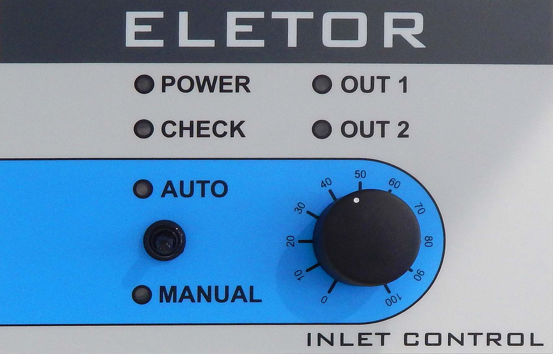 | Indicator POWER – indicates that power is present and the batteries are charging. 1.Indicator CHECK – lights continuously in automatic mode when the controller signal is passed to the output; flashes when the signal from the knob is supplied to the output. 2.OUT 1 – indicates abnormal conditions in channel 1. 3.OUT 2 – indicates abnormal conditions in channel 2. 4.AUTO – automatic operating mode. 5.MANUAL – manual operating mode. 6.Knob 0%-100% - selection of the air inlet opening level. |
Error and warning messages
Error messages inform the user of abnormal conditions in device operation. The possible error messages are listed below:
- Indicator POWER – not lit green – no mains power.
- Indicator CHECK – flashing yellow – the signal from the potentiometer is supplied to the outputs.
- Indicator OUT 1 – lit red - an abnormal condition has been detected (no control signal, short circuit at the output or short circuit on the 24VDC bus) in the first channel.
- Indicator OUT 2 – lit red - an abnormal condition has been detected (no control signal, short circuit at the output or short circuit on the 24VDC bus) in the second channel.
Notes and warnings
The electrical power supply must be disconnected during installation of the device, as the voltage on some components poses a danger to life and health. It is recommended that installation be entrusted to a qualified person.
- To avoid problems with device operation, the manual must be read before installation and use. Do not tamper with the design or perform repairs yourself. This applies in particular to modifications of parts and components.
- Maintenance or servicing must be performed by authorized personnel (an installer or the manufacturer's service department). An alarm system is required in livestock buildings with forced ventilation.
- The device manufacturer is not liable for damage caused by incorrect installation, incorrect programming of functions, the consequences of unforeseen events or external factors. The device parameters must be set according to the conditions in the livestock housing.Settings are individual and depend on the livestock farmer's decisions.
- The device manufacturer reserves the right to make changes to the device design and software. The device includes a battery bank; excessive discharge must be prevented, as it may damage the batteries. Short-circuiting the battery terminals may result in a fire.
 At the end of its service life, the product must not be disposed of with unsorted municipal waste, but must be disposed of in accordance with applicable regulations (European Union WEEE Directives 2012/19/EU). The product has been manufactured in accordance with RoHS requirements (European Union Directive 2011/65/EU).
Controller technical specifications
| Parameter | DESCRIPTION |
|---|---|
| AC supply voltage | 85 |
| DC supply voltage | 120~370VDC |
| Output voltage | 27,6VDC |
| Maximum output current | 1,8A |
| Efficiency | 85% |
| Maximum current of 0-10V | control outputs 30mA |
| Maximum ALARM output (contact) current | 3A |
| Input and output surge protection | YES |
| Short-circuit protection | Automatic |
| Battery bank | 4Ah 24V |
| Operating temperature range | -10 +40oC |
| Device dimensions | 20x15x8 cm |
| Enclosure ingress protection rating | IP65 |
The IC-AC controller is supplied with:
- wall plugs - 4 pcs.,
- batteries 12V 4Ah - 2 pcs.,
- cable gland PG13,5 - 1 pcs.,
- cable gland PG11 - 3 pcs.,
- cable gland PG9 - 3 pcs.