Controller IC-AC
Controller for air inlet actuators and lifting systems based on bidirectional AC motors with a potentiometer for reading the current position. The controller converts the 0-10V signal into the inlet opening level and also allows manual control.
Parameters and features:
- Operating modes:
- MANUAL – manual control using the “+”, “-” buttons;
- AUTO – automatic operation within the calibrated range, proportional to the 0-10V signal;
- EMERGENCY – if the control signal is lost, the air inlets open to a preset percentage level;
- Relay output (forward/reverse) 2A;
- Control signal: 0-10V;
- Control signal inversion available;
- Position measurement using a 1-100kΩ potentiometer;
- Programmable hysteresis and reading averaging time;
- Sealed enclosure IP56;
- Supply voltage 230VAC 50Hz;
- Menu languages:
- Polish
- English
- Ukrainian
- Russian
Controller installation
The electrical power supply must be disconnected when installing the device, as the voltage present on some components poses a danger to life and health. It is recommended that installation be entrusted to a qualified person.
Selecting the installation location
The installation location must be selected carefully, ensuring easy access to the device for authorised persons while keeping it inaccessible to animals and children. Climatic conditions must also be considered, i.e. the device should operate within the temperature range of -10°C to 40 °C, in a location not exposed to direct sunlight.
Mounting
The device can operate in harsh climatic conditions. When correctly mounted, the device is resistant to harmful environmental effects.
During mounting, attention must be paid to the following:
- the cover must be secured with all screws tightened,
- the cables used to connect the device should have a round cross-section,
- after connecting a cable, tighten the cable glands so that the cable is sealed and secured against movement; the use of silicone is recommended,
- unused cable entries (cable glands) must be plugged,
- secure the lower part of the enclosure to a flat wall using 4 wall plugs.
Electrical connection
Before connecting the system, make sure that the power supply is switched off!
After unscrewing the device, remove the front panel. To do this, unplug the ribbon cable from the connector marked P1. Feed the cables through the rubber cable glands and proceed with their connection. Make the connections as described. The controller terminals are shown in the figure below.
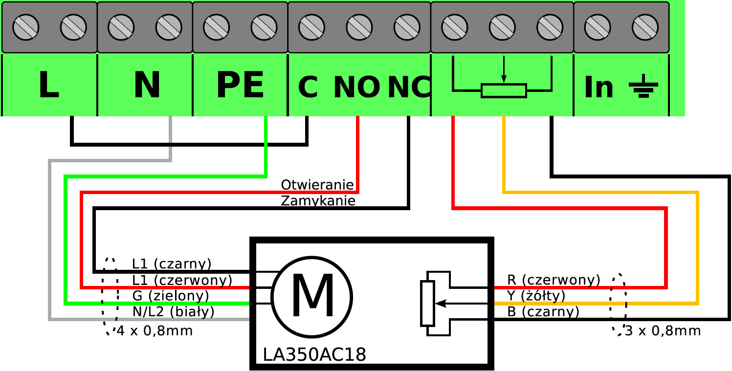
Connect the 230V AC power supply from the distribution board to the following terminals:
- L connector live terminal. A circuit breaker (type “S” B3) and surge protective devices are required.
- N connector neutral terminal.
- PE connector protective earth terminal.
Actuator output:
- L connector connect with a wire to connector C to supply voltage to the relays.
- N connector actuator neutral terminal.
- PE connector actuator protective earth terminal – enclosure.
- Connector NO actuator terminal for the air inlet opening direction.
- Connector NC actuator terminal for the air inlet closing direction.
- Potentiometer connector – connect according to the markings on the actuator diagram. The potentiometer supply polarity must be selected so that the position units increase when the air inlets open and decrease when they close. If this is not the case, swap the potentiometer supply wires.
- In connector – connect to the controller to supply the control signal to the lifting systems.
Operating principle
In automatic mode, the controller converts the control signal in the 0-10V range into the corresponding air inlet actuator position. The actuator must be calibrated at the fully open and fully closed air inlet positions. During calibration, ensure that the cables running to the air inlets remain under continuous tension. During calibration, the “+” button must open the inlets and the “-” button must close the air inlets. If this is not the case, swap the wires at terminals NO and NC. The positions read from the potentiometer for opening and closing should differ by more than 100 units. The position units read from the potentiometer must increase when the inlets open and decrease when they close. If this is not the case, swap the potentiometer supply wires. After correct calibration, the controller is ready for automatic operation and will control the actuator position. Applying a control signal below 1,5V results in the air inlets being set to the emergency position.
Operation
The air inlet controller can operate in one of two modes: manual or automatic. The selected operating mode is stored and is unaffected by a power failure – after power is restored, the controller returns to the mode in which it last operated. The currently selected operating mode is indicated on the display:
- MANUAL - pressing and holding "+" or "-" activates manual mode. In this mode, the air inlets are controlled manually using the buttons: “+” - opening, “-” - closing.
- AUTO - pressing and holding "Esc" activates automatic mode. In this mode, the inlets operate automatically, controlled by the 0-10V signal from the In connector.
Basic menu functions
| MENU | Description |
|---|---|
| MANUAL STOP POT 539 | “Information mode” – for manual operation. Displayed information: - STOP – actuator stationary; - OPEN – air inlets opening after pressing the “+” button; - CLOSE – inlets closing after pressing the “-” button; - POT 539 – current actuator position parameter determined by the potentiometer. •Switch to automatic operating mode by pressing and holding the “Esc” key |
| AUTO 20 % = In 3,70 POT 511 | “Information mode” for automatic operation. Displayed information: 20 % Air inlet opening position setpoint "=" air inlets at the set position "–" inlets closing to the specified position "+" inlets opening to the specified position In 3,70 control voltage measurement at the In terminals POT 511 current actuator position parameter determined by the potentiometer. Switch to manual operating mode by pressing and holding the “+” or “-” key |
| Emergency Flaps 30 % | “Emergency flaps” – sets the emergency opening value for the flaps (air inlets) in the event of control signal loss. The air inlets will open to the preset level in the event of a controller or signal cable failure. |
| Opening Calib 671 -> 311 | “Opening calibration” – air inlet opening is calibrated by setting the maximum opening (end position) of the inlets using the “+” and “-” buttons. The first displayed value represents the last saved setting, and the second value represents the current actuator position. The “Ok” key saves the entered settings to memory; “Esc” exits calibration mode without saving. |
| Closing Calib 281 -> 311 | “Closing calibration” – air inlet closing is calibrated by setting the minimum inlet position using the “+” and “-” buttons. The first displayed value represents the last saved setting, and the second value represents the current actuator position. The “Ok” key saves the entered settings to memory; “Esc” exits calibration mode without saving. |
| Averaging Time 5 s | “Averaging time” – averaging time for the control signal from the In connector, providing protection against oscillations at the control input. |
| Inversion No | “Inversion” – enabling this function adapts the controller to the 10-0V control signal |
| Language Polish | “Language” – menu language selection |
| Pot Hysteresis 5 | “Potentiometer hysteresis” – changes in the actuator position parameter below the set value are disregarded during positioning. This parameter is intended to eliminate very small actuator movements and interference from the potentiometer. |
Notes and warnings
The electrical power supply must be disconnected when installing the device, as the voltage present on some components poses a danger to life and health. It is recommended that installation be entrusted to a qualified person.
- To avoid problems when operating the device, the instructions must be read before installation and use. Do not interfere with the design or carry out repairs yourself. This applies in particular to modifications to parts and components.
- Maintenance or servicing must be performed by authorised personnel (an installer or the manufacturer's service department). An alarm system is required in livestock buildings with forced ventilation.
- The device manufacturer is not liable for damage caused by incorrect installation, incorrect programming of functions, the consequences of unforeseen events or external factors.
- The device parameters must be set according to the conditions in the livestock housing. These settings are individual and depend on the livestock keeper's decisions. The device manufacturer reserves the right to make changes to the device design and software.
 At the end of its service life, the product must not be disposed of with unsorted municipal waste, but must be disposed of in accordance with applicable regulations (European Union WEEE Directive 2012/19/EU). The product has been manufactured in accordance with RoHS requirements (European Union Directive 2011/65/EU).
Controller technical specifications
| Parameter | DESCRIPTION |
|---|---|
| AC supply voltage | 230VAC 50Hz |
| Maximum output current | 2A |
| Output interference suppression filter | RC |
| Input impedance | 100kΩ |
| Input and output surge protection | YES |
| Potentiometer power supply | 10VDC |
| Maximum potentiometer output current | 30mA |
| Operating temperature range | -10 +40oC |
| Device dimensions | 20x15x8 cm |
| Enclosure ingress protection rating | IP65 |
The IC-AC controller is supplied with:
- 4 wall plugs,
- 2 PG11 cable gland,
- 2 PG9 cable gland.